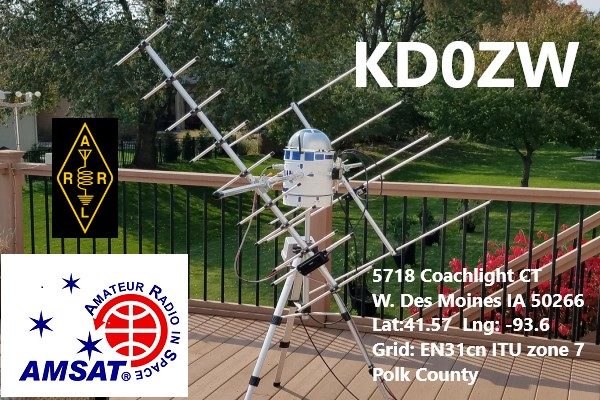
SAT TRAC 32 — In service 3/26/2022
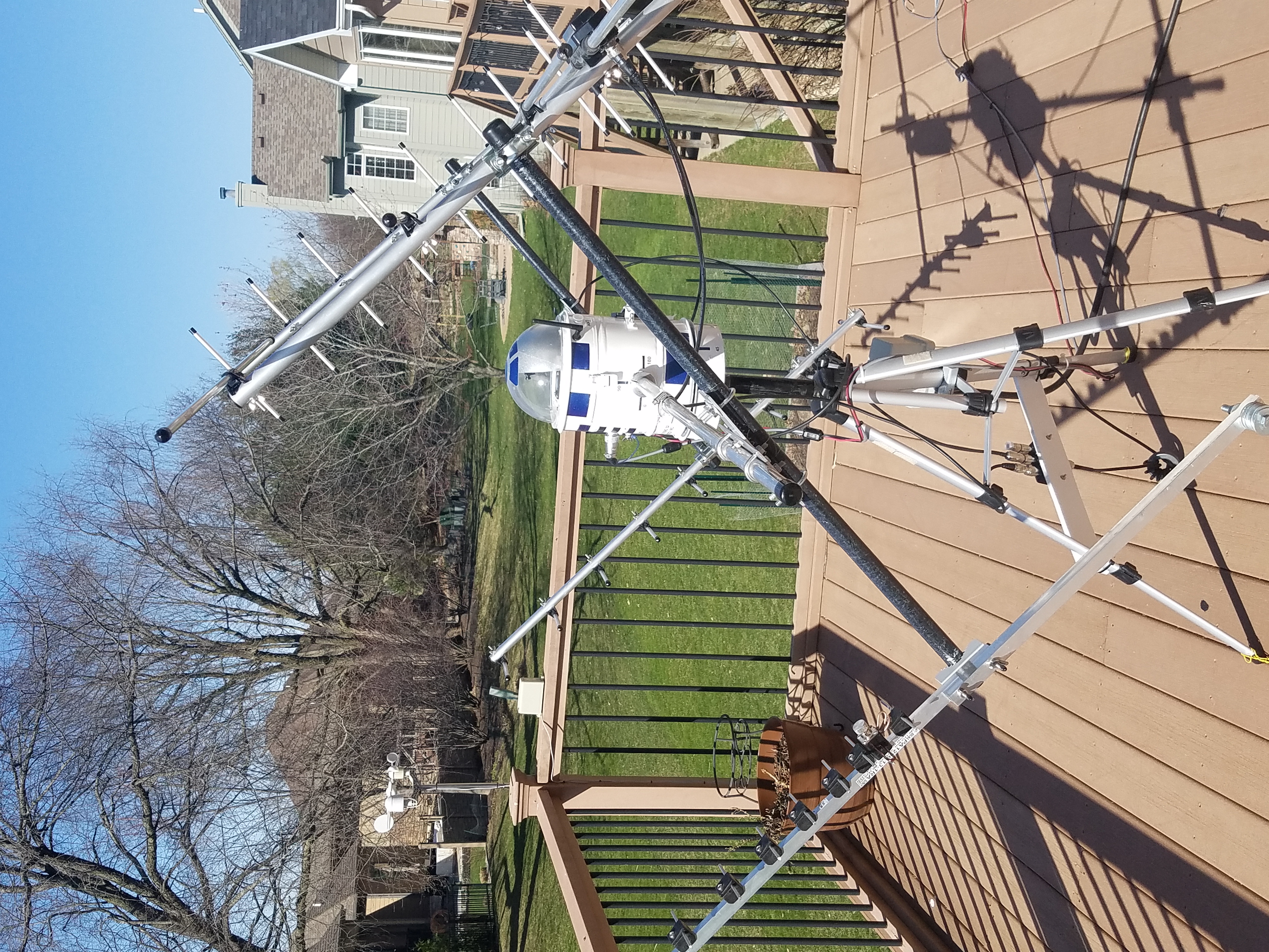
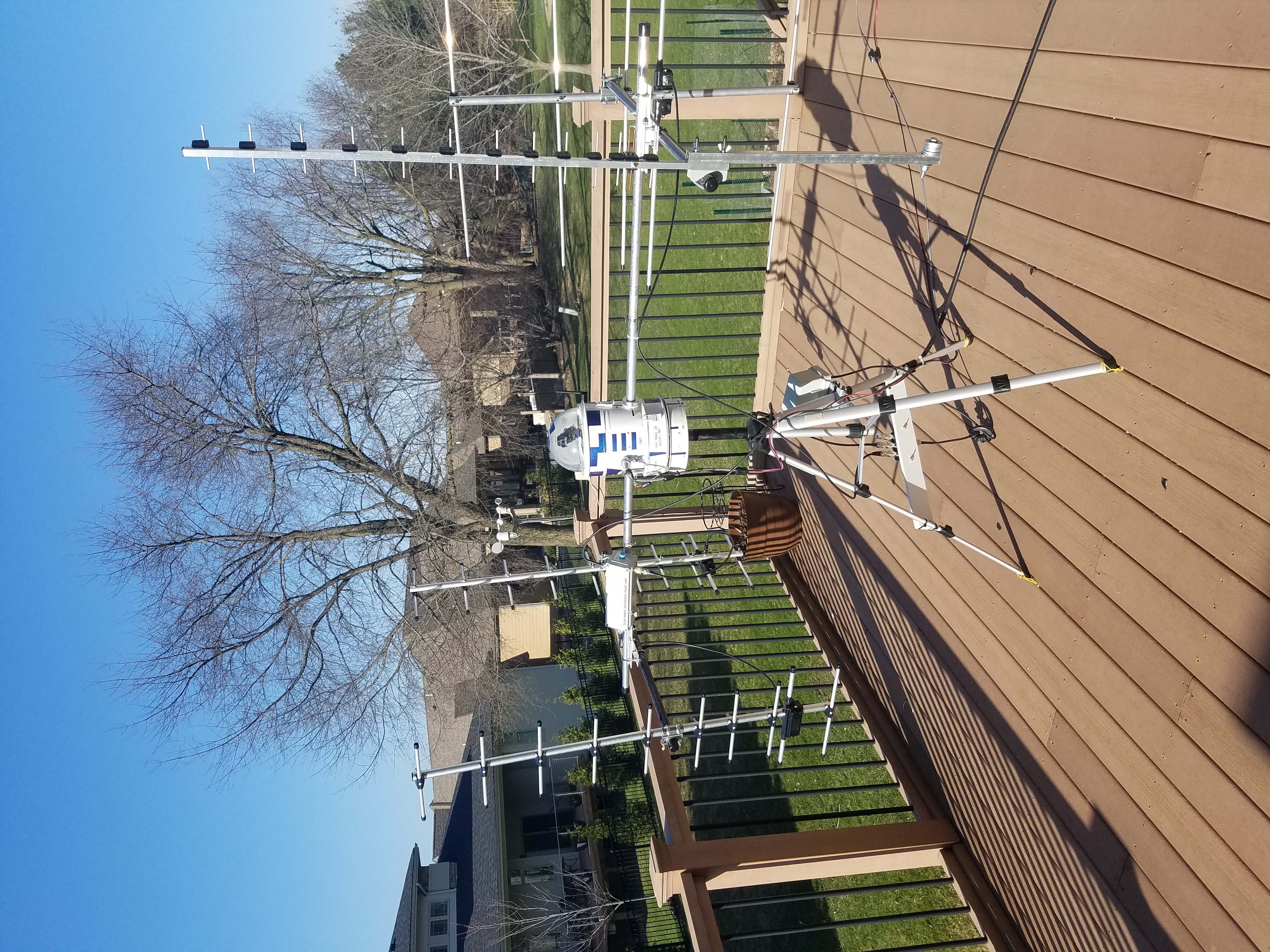
Okay… I’m ready to move ‘ZW3’ — SAT TRAC 32 to the deck…
Update: 4/2/2022 — Deployed and making contacts!
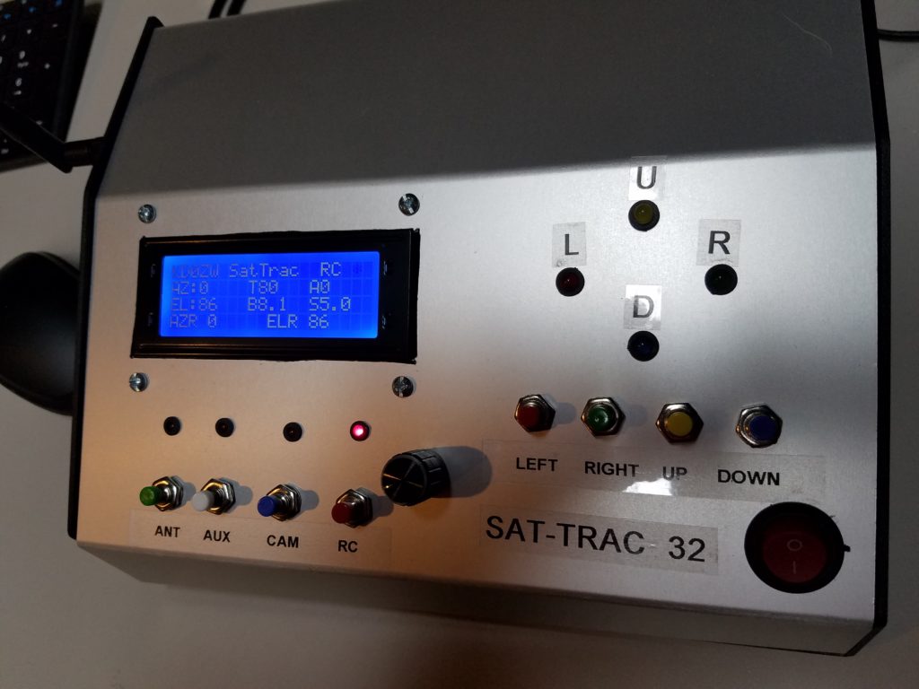
Here it is:
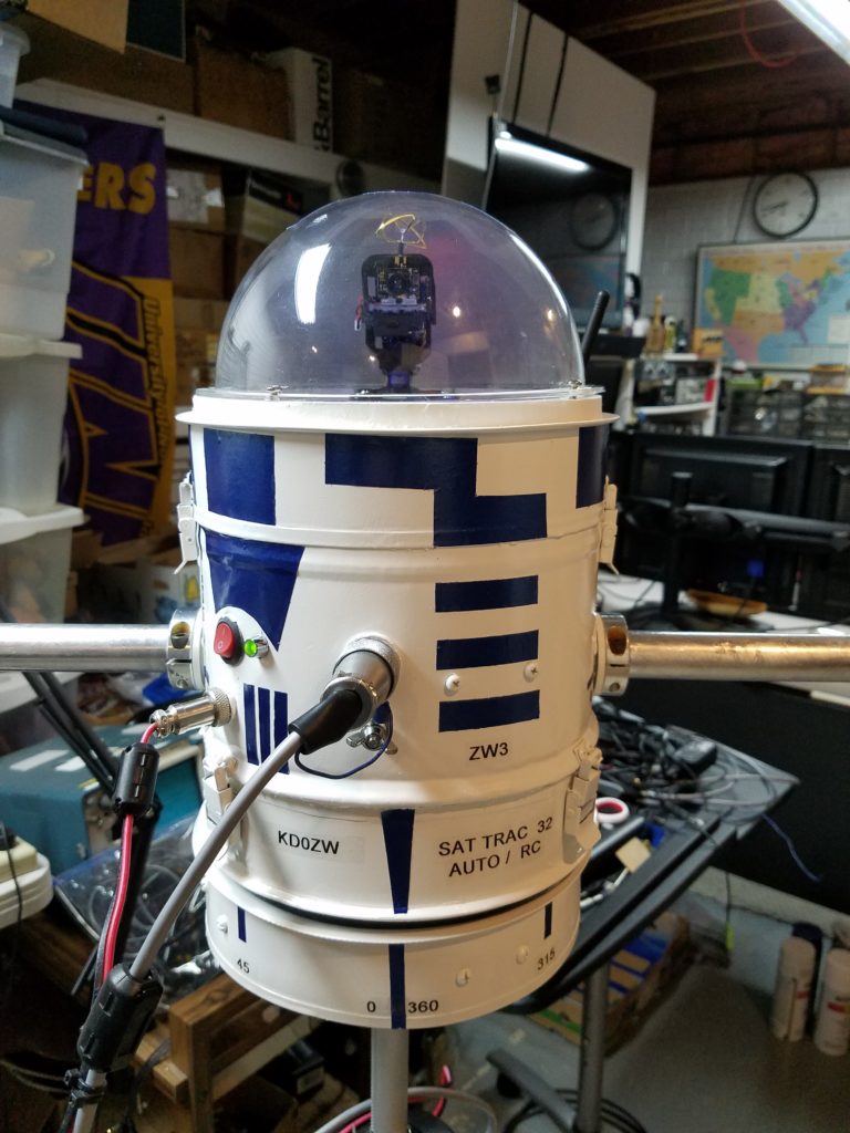
It’s about 1/2″ taller than my 8-bit unit… but has so much more to offer like:
- 32 bit Arduino Due — 84mhz, 3.3v logic, (2) DAC’s, (12) Analog ports, utilizes 80% of existing 8-bit code — 6-7 times the speed compared to an 8-bit Arduino Mega 2560.
- DMA-> programming to process digital data to DACs. Also, DMA-> programming for much-improved analog reads for the auto-calibration system.
- Multiplexed AS5600 chips to get rid of analog pots for a touchless solution impervious to wear, temps, and gives you 12bit accuracy.
- 4 independent buck power supplies to reduce stress on Arduino Due. Low ripple too.
- External 256k I2C EEprom was added to record data every 5 minutes.
- ITR20001/T IR sensors to auto-calibrate for AZ & EL on startup. FET switch to turn off after calibrating.
- Mechanical EOT switches and watchdog programming shut down the system if errors are detected.
- 30A logic level FET switching for 12v and 5v loads.
- Buffered inputs and (2) bus control chips to toggle Auto computer control & RC manual control
- Programable 3 channel PWM generator to get the right setting for smooth operations.
- 7A double H-bridge motor controller. PWM complements the motor driver!
- Switching from CP, to (HP or VP) can be done from the controller. Very convenient. GHz grade relays.
- Ball Bearing Fan drawing from the internals over the camera and out the back. Works nice. Temp controlled with BMP280.
- DACs protected with 3k 1% resistors
- Low power consumption when idle. Approx 13.6 @ 180ma. Full load everything running approx 650ma.
- HD camera working at 5.8ghz. 3 settings 50mw, 100mw, 200mw
- LEDs in the bubble to see action at night.
- All functions are available to Auto direct connect and RC mode. RC mode does show temps for board voltages for the 3.3 v logic and the 8v input to the Arduino Due.
- 10rpm worm drive motors are pulling 100-120ma each under load. Very low. Also, the 12v DC motors work fine in cold weather. 0 to 360 azimuth can be set for a 56-90 -sec trip. Approx. .5 to 1 r.p.m
- Nrf24L01+LNA+PA for RC control up to 1000 meters.
- All momentary buttons on the controller are debounced and buffered.
This is pretty much the fun stuff I could put in the can. The ITR20001/T IR auto-calibration system makes the system work well. The multiplexed AS5600 sensors read the position of the diametric magnets from 0-360 with 12-bit accuracy. The Curious Scientist on YouTube can provide you with the logic to keep track of multiple turns, speed, etc. He uses his software with stepper motors. Okay, I adapted it for use with a 1/4″ chain system. The sensor detects 2.5 rotations for 360 degrees. So, when the system starts up, it reads where the magnet is and tears off the position establishing and determining this is the zero spot. So in reality, should the power be cut at say 90 deg AZ & 90 EL, for example, it would become 0 AZ & 0 EL after restarting. Not good… So the auto-calibrate system is the answer. This is totally my brainchild. It’s a little more involved than it needs to be, but, pushing the envelope and having fun, I implemented my idea.
Solution:
Yep, I don’t think you’re going to see this too often in a SAT Tracker! The process:
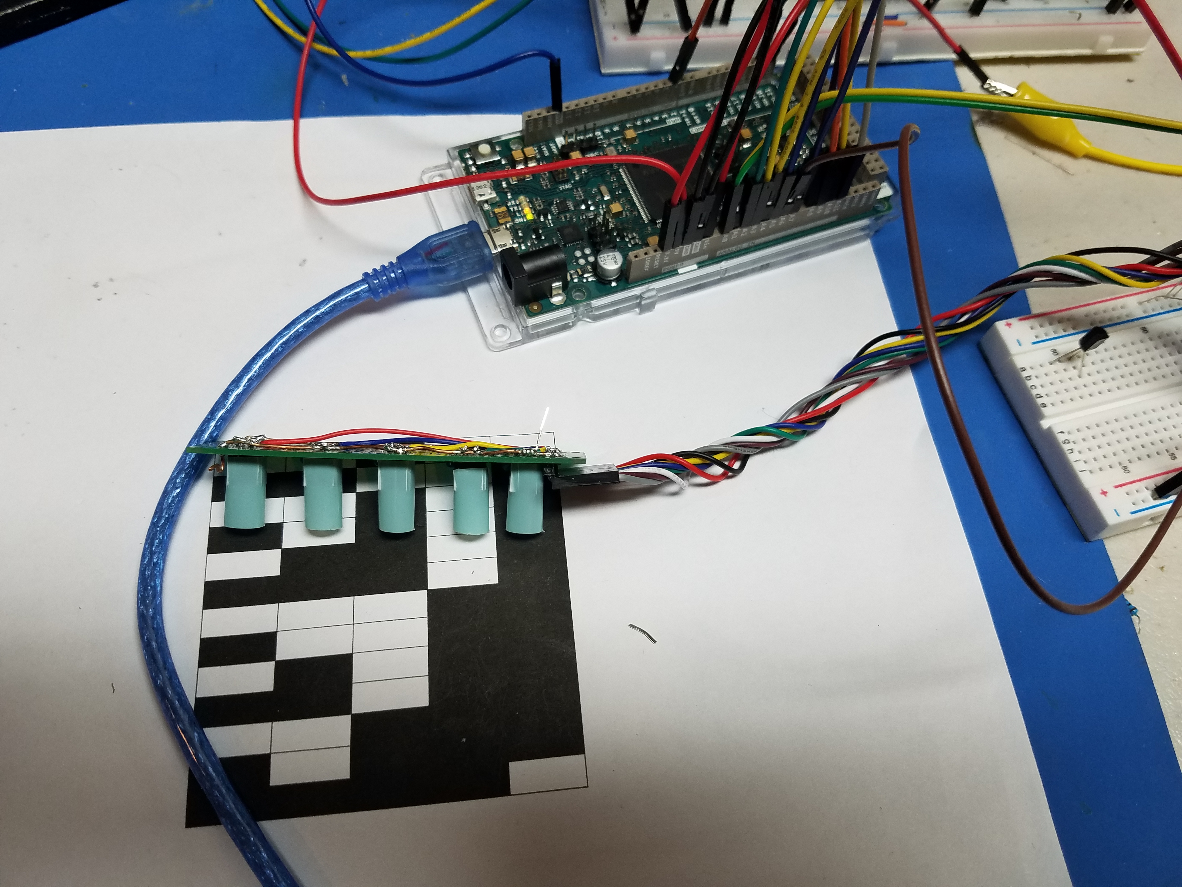
- Make a table with your favorite spreadsheet. 4 x 12 that has a total width of 1.1 inches *3.1416. This will wrap around a nice alum 1″ boom. Print it in black & white. No grayscale or color settings. I used an Epson ET-3760 inkjet. IR detection works great.
- Each column is a binary position. Columns 1-12 represent 0-360. 30 degrees per column.
- Make a circuit with IR sensors that align with each row. I used 4 sensors as the 5th could be used as a sort of a confirmation… If sensors are all LOW (AND/OR) #5 is HIGH we are indeed at zero! Totally optional to add a 5th sensor.
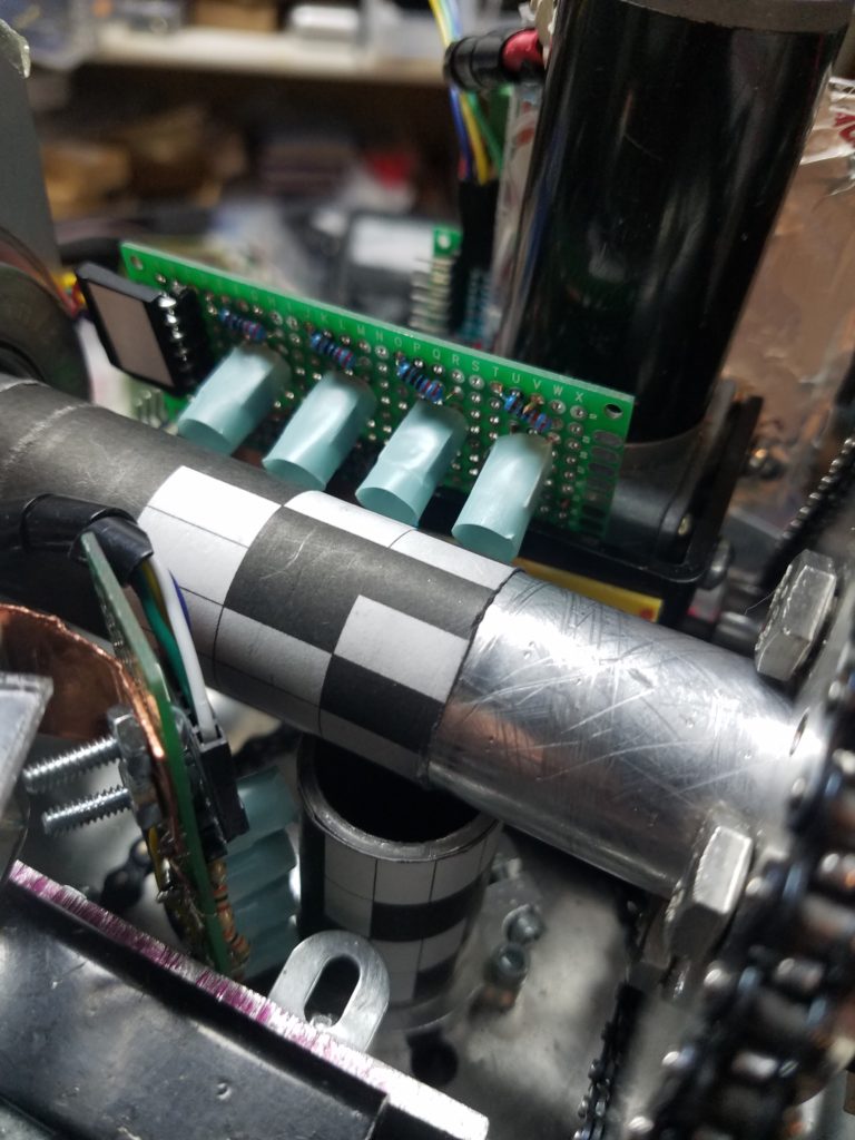
- Use 8mm straws or shrink tubing to narrow the IR LED and the IR detector. Use your smartphone camera to view the LEDs. Using 3.3v, you will see a near IR LED that is a light violet color.
- Position perpendicular, if possible, to the binary representation on the tubing. Space 5-8 mm from the sensor. Mounts must be ridged to maintain consistency.
- Program DMA to take multiple samples very quickly at 1 RPM to get the best average number. I take 20 samples and average as it moves. Convert numbers for each sensor to an H or L (1 or 0).
- From sensor one to 4, simply calculate the binary number to a decimal.
- Use an array to translate the binary->Decimal number to degrees. Once the degrees are known, a timer can be established to watch the progression to the landing area, 0 AZ, 0 EL. Should we time out when calibration, the system will restart and try again.
- Progam a PWM generator to let your motors crawl to the perfect start position. It lands on my 0 binary positions every time.
- If you want the ultimate system utilizing these ITR20001/t sensors I would suggest using a nice quality miniature pot to calibrate each sensor individually. In a perfect world, you could do that… I chose to be close so all sensors at a certain level would be considered a 1 or 0. This approach will address the possibility of a change of physical distances when scanning. 1-3mm of the additional distance between the sensor and the target will change the 12bit number.
- After the system is at the designated landing area, the AS5600 logic sets everything to zero. We are perfectly calibrated.
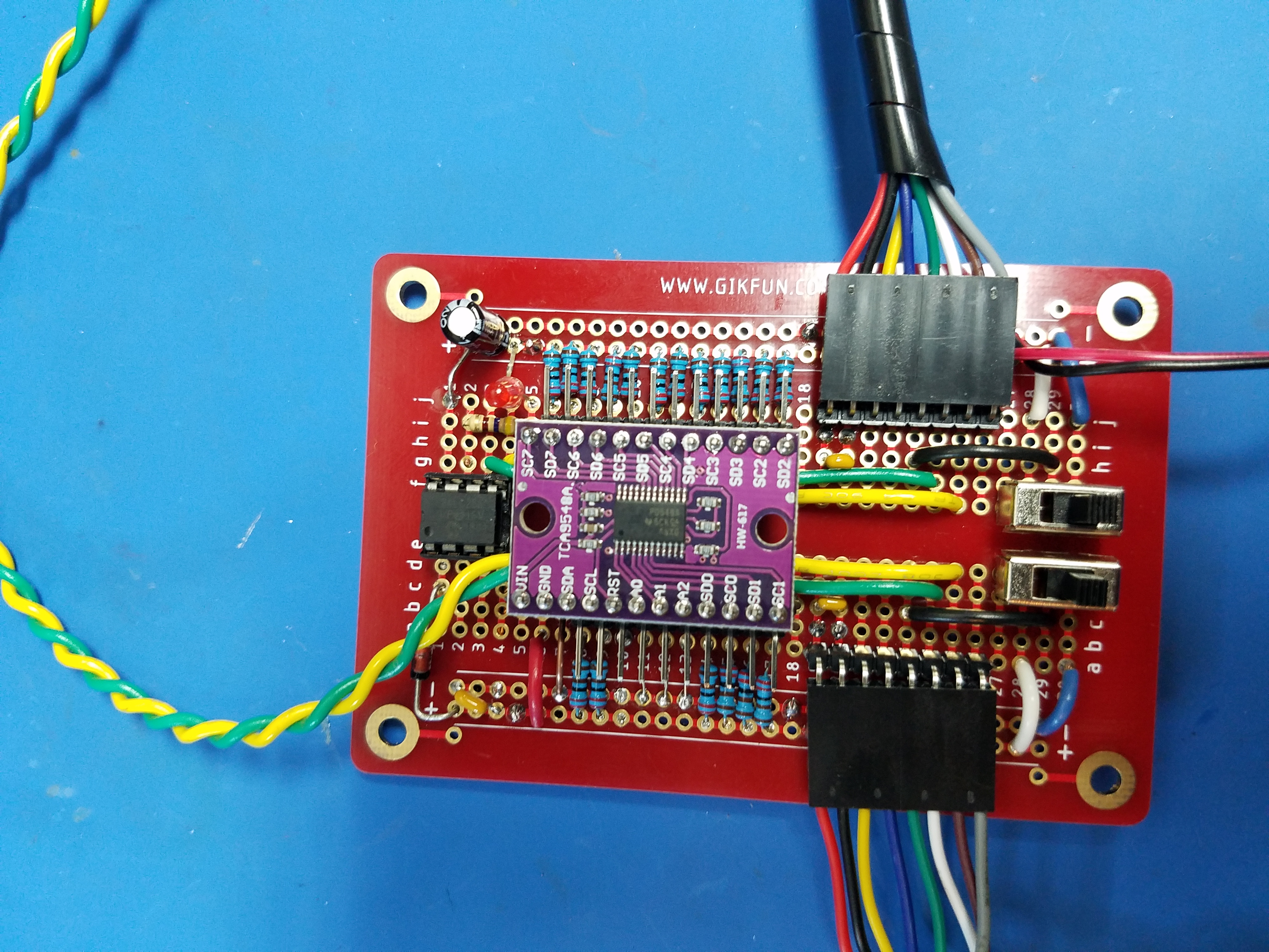
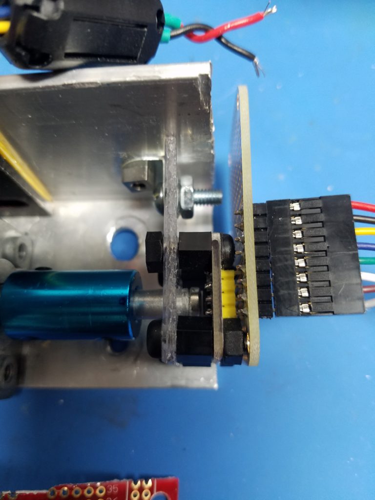
Here is how the AS5600s are installed:
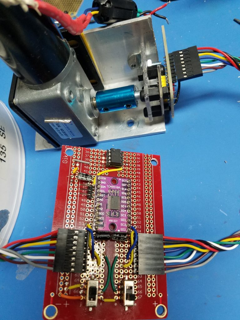
Using an 8 ch I2C multiplexer (TCA9548a), you load it up with AS5600s, BMP280, or whatever you want. It’s pretty easy to select channels. You need to make your board as stable as possible. Bypass caps like a .1uf cap and 3.3v Zenor across power input can protect against line noise and excessive voltage. This was an early board where the multiplexer was soldered in. Bad move, zapped it with a static shock. Use a socket or female header. The switches allow for direction changes in reading the sensor… Nice feature. Run at 100k samples/sec (SPS). I’ve run it at 400k/SPS. For best stability, run it at normal I2C speed. Plenty fast. Tip: Make sure your I2C connection to the motherboard is solid. Flakey connections will cause intermittent errors.
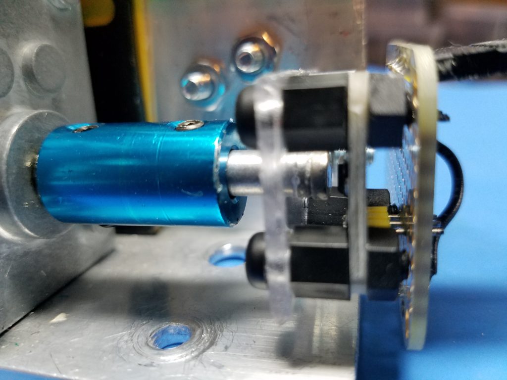
Another look: The diametric magnet is a little close here: Use your serial monitor to see the report code from the sensor. It will tell you when it’s too strong. It told me I was too strong so I gave it some distance. Mine is 4-5mm away from the sensor. Some sensors come with a 3mm diametric magnet. I’m using 6mm diametric magnets that I attached to a 6.35mm (1/4″) aluminum shaft with Loctite marine adhesive. Tip: I’m using a polycarbonate plastic mount, and nylon mounting hardware to attach the sensor. Keep ferrous metals away from the sensor. You don’t want to skew the magnetic flux.
The 32-bit computer with the IR calibration system and the multiplex AS5600s has really improved accuracy and made this a challenging project. Another big change from my previous 8-bit machine is the programmable PWM generator and the 7A DROK dual H-bridge DC motor controller. Previously, I used an optoisolated 12v relay array to click in relays. I used a fixed frequency motor speed controller to keep the motors running real smoothly. Using a 32-bit computer with 3.3v logic requires noise and ripple to be kept under control for stability. Relays make too much racket for I2C and the computer in general. You will see the noise enter the system from all angles. All control inputs will have 1k resistors and 3.3v Zenors to start. Then they will enter buffers to keep the signals crisp and square before they are routed with the bus chips. Failure to do this can pop chips, boards, Dacs, or add noise that will disrupt processing.
Final Thoughts:
This is a full-functioning SAT Tracker. Future ideas to add to it will be software-related. I have a weather station that is tethered to a Rpi. I will convert it to 2.4ghz and send it to my controller so I can see wind speed, direction, rainfall, UV, or whatever else I want to add. I think that info from the controller would be helpful in the operating position. This project has got me pretty acquainted with the NRF24L01+. Running at 1MPS data can be retrieved reliably from 35 meters out.
Hope you have enjoyed my adventure and it has given you the maker bug… Catch you on the Satellites!
73,
Mike