SAT TRAC – Part 3 Making the prototype
Part 3: Making the prototype
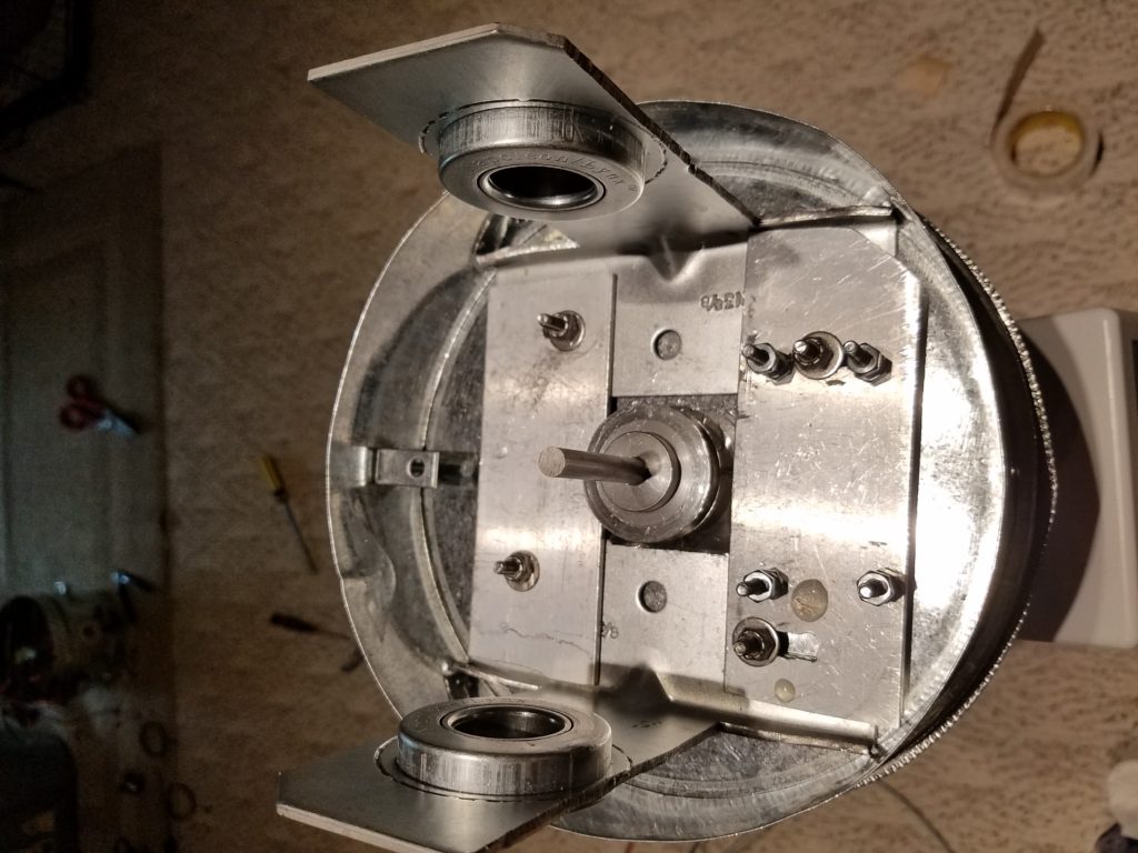
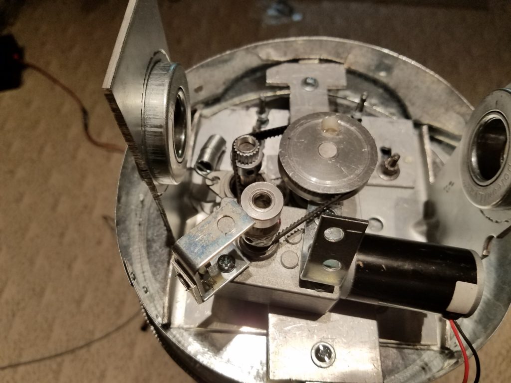
After developing a wishlist, I had to come up with some kind of rotating base that also had the ability to elevate. I found some high-density foam and cardboard and made a square platform. Buying some linear actuators from Amazon, I thought for sure I was on course. Well, getting the actuators to rotate a platform 360 degrees and elevate 90 degrees is possible, but the unit was unsightly, a big wind load, not portable, and not weather resistant. And of course, not quick. So the approach was scrapped. I saw other projects made from robotic-type girders that seemed pretty huge and not portable. Other examples used analog TV rotors offset to get the AZ and El capabilities. Additional add ons were used for positioning. If I put something like that on the deck, my wife (XYL) would have a cow. Better nix that. So all of these ideas bounce around in the thinkolator. I walked through home decor stores, thrift stores, discount stores, and a couple of home improvement stores to get some idea of how I could make this SAT-TRAC unit. Nothing was giving me the vibes. Until I walked thru the HVAC aisle at the home improvement store. Short round steel sleeves and caps in 8″ or 10″ sizes. Images of sputnik or R2D2 entered my head. I bought the 8″ tube with 3 caps. 2 caps for the base, a tube for the body, and a cap for the top. It will look like a large coffee can! But if I find a plastic bubble for the top then I could install a camera…Now that’s putting the cart way in front of the horse. Let’s just work on the base and build it. I found a 200lb capacity lazy susan, and contemplated motors to spin and position the AZ. The natural choice would be stepper motors. However, they take the current to move and hold the position. Two nice-sized stepper motors are heavy and not very smooth. I chose two 10rpm DC reversible worm drive motors. They are inexpensive, can operate in the cold, and don’t require a lot of additional circuits to work. Since the motors have 8mm shafts, I could use 3D printer gears, one with 60 teeth and the drive cog with 20 teeth They would be connected by rubber timing belts. A precision 5K pot was intended to take up belt slack and provide analog input to the Arduino nano. Below is the Base that was started. Notice the two 1″ garage door flanges to support the boom…So now we have both imperial and metric to deal with.
Well did it work… Kinda… the base rotated a little and the precision pot gave us some data and then the base started to pull to one side and bind and the belt started to skip on the teeth… And soon the inexpensive pot was toast as the lateral pressure on it broke it apart. Fail, Fail, Fail…
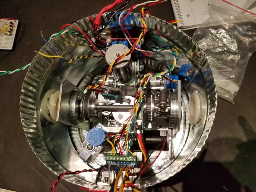
I had to retool… My design just wasn’t cutting it. The base rotating above the bottom cap worked but the binding was caused by pulling the base in one direction. I found that my 20 tooth drive gear was not staying perpendicular to the stationary 60 tooth gear, and not keeping enough teeth on the belt. So I put a longer axle in the center and put another 60 tooth gear on top. I replaced the single axle worm drive motor with a dual axle motor with a 20 tooth drive gear. The pot was removed and replaced with a flange-bearing idler for both sets of gears to remove any slack on the belt.
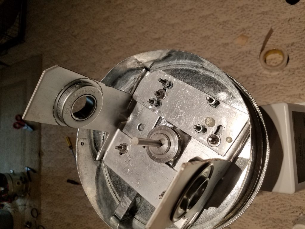
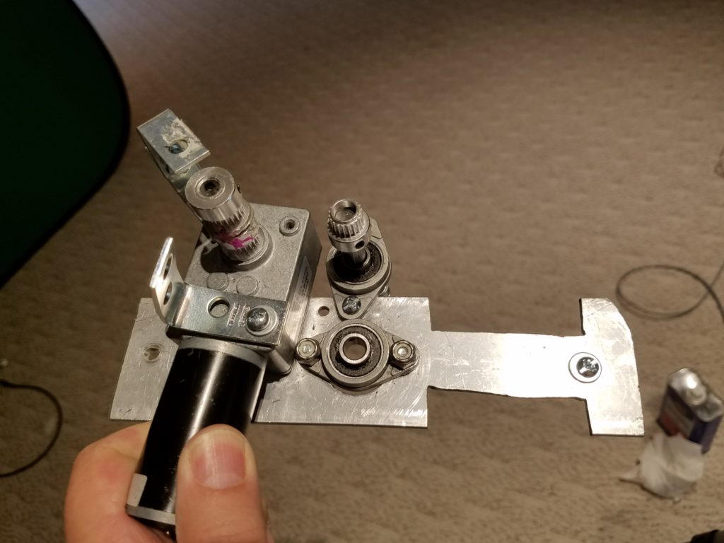
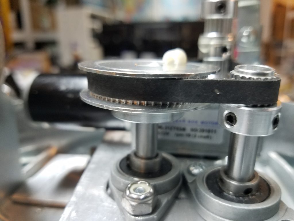
10rpm motor on alum bracket with idle wheel and bearing.
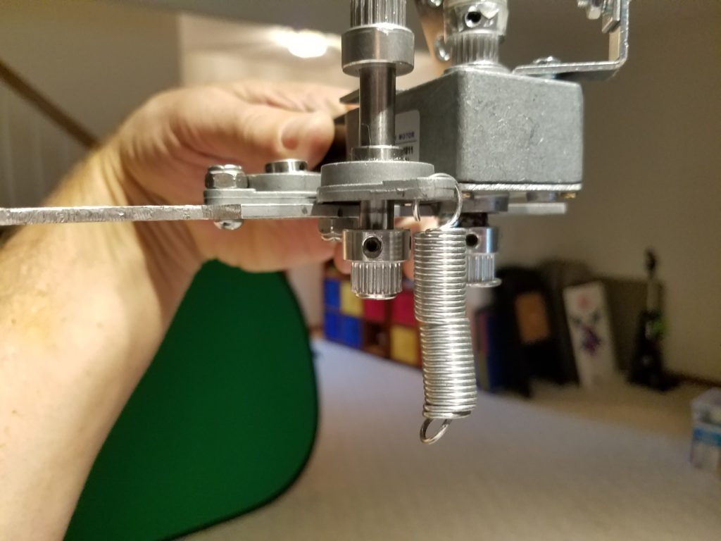
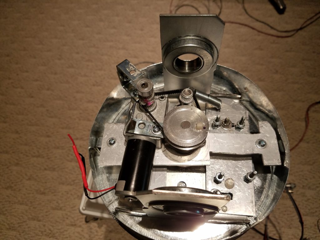
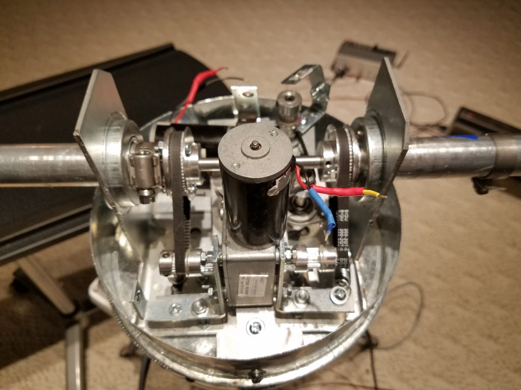
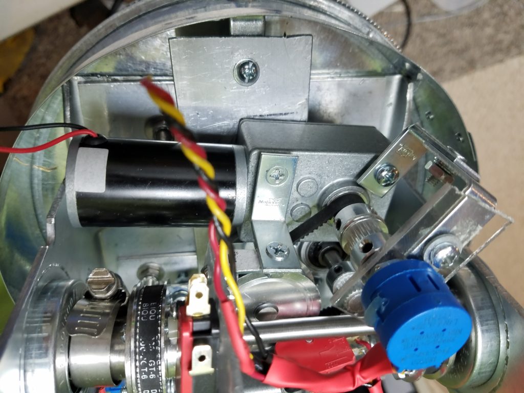
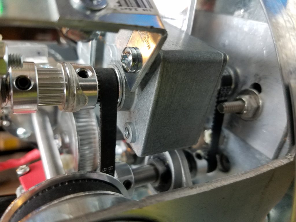
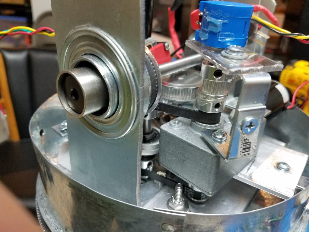
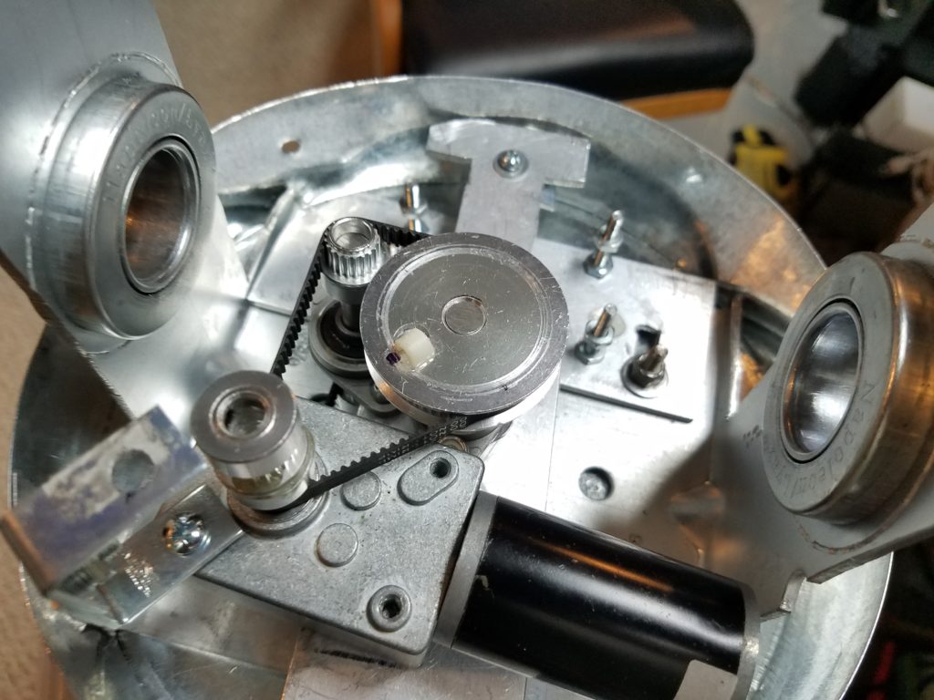
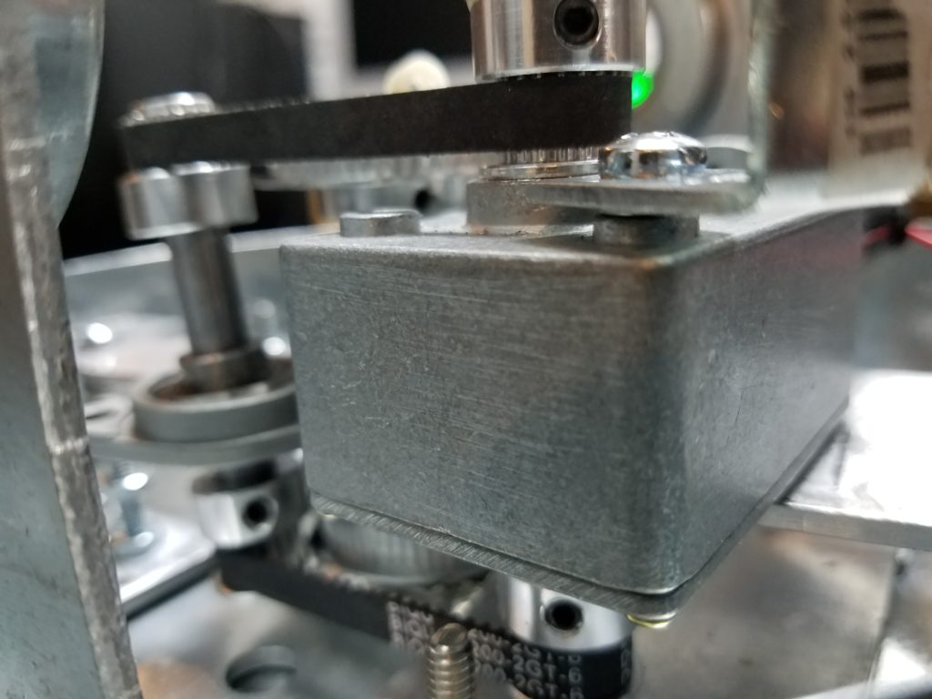
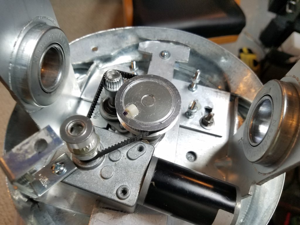
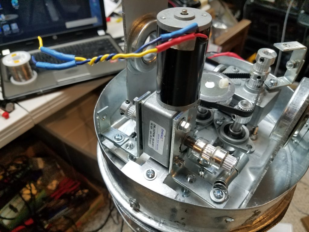
Results: The base operated smoothly pulling 180ma@ 12v at full power while rotating around the base. The pot would be mounted on top of the 20 tooth drive gear without pressure on any plane. The motors had plenty of power, but keeping everything accurate and stationary through its range is the challenge. Fortunately, I won this battle. I bought another dual axle motor for the elevator mechanism. I didn’t want to go thru this again.
Here is a picture looking down from the top: