Station Antenna’s
One of the more perplexing items to being a successful amateur radio operator is what antenna should I use. There are more opinions on the subject as there are amateur radio enthusiasts. Everything is a compromise. HOAs, small lots, height restrictions, unfriendly neighbors, metallic structures, etc. Like most operators, it’s a challenge to get the most out of any antenna. For many years I used well-known verticals like the 14 AVQ and Hustler 6BTV. Like many will tell you, they radiate poorly in all directions… However, laying out your radials can change that too. For contacts in North America, verticals work fine. Unfortunately, neighbors, HOA, and the weather are usually not on your side. That’s why I use 22-24 gauge wire.

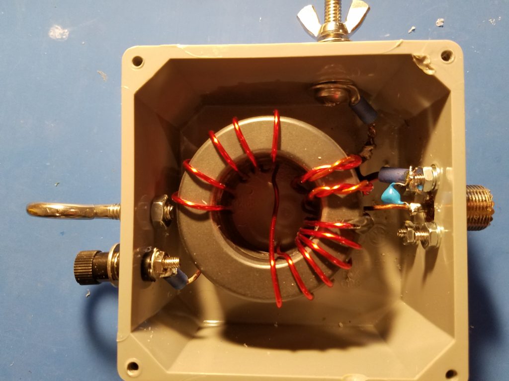
Here is the HB RF transformer I’m using. It uses 3 T240-52 toroids. K1RF Steve Dick did a nice slide show presentation on how to make it. I’m using 14ga. enameled wire with a 100pf 10KV cap across the input. According to Steve’s work, I would see a 92 to 98.2 efficiency rating. Also, using 3 toroids, he says I should be good up to 1 KW! So 1 to 100 W should be good, eh? Thanks, Steve.
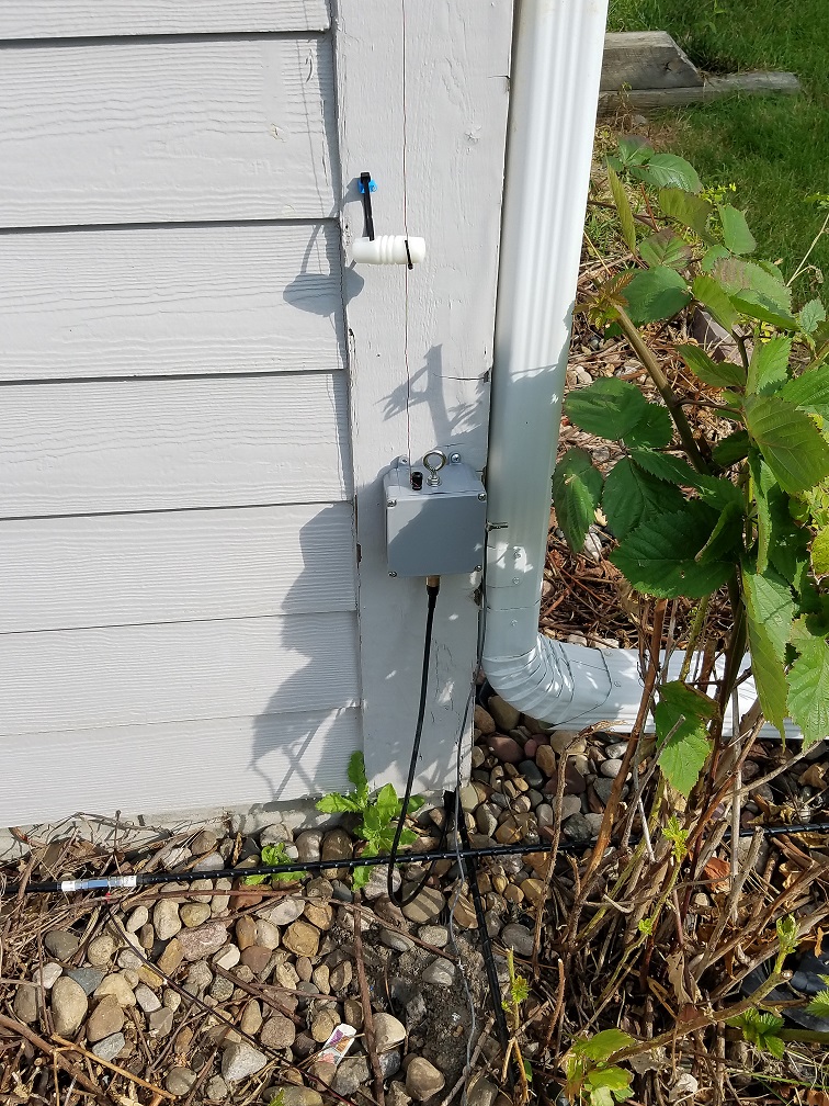
My Inverted L gets me to all corners stateside with 30 watts on all HF bands! Must be working okay! The plans are to feed a resonate wire for the longest wavelength you will use… In my case, it’s 40mtrs or approx 67 ft. I didn’t want it up 12ft from the ground so I left it 74ft! More is good right? Still works fine with a tuner.
I do have the 6BTV on standby… Maybe I need a flag pole in the front yard… hmmm.
Or maybe add satellite communication capability?
Poof —- TADA
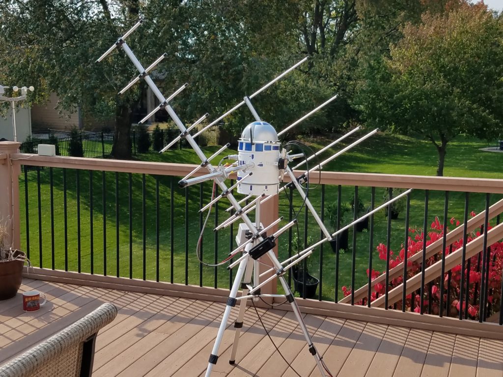
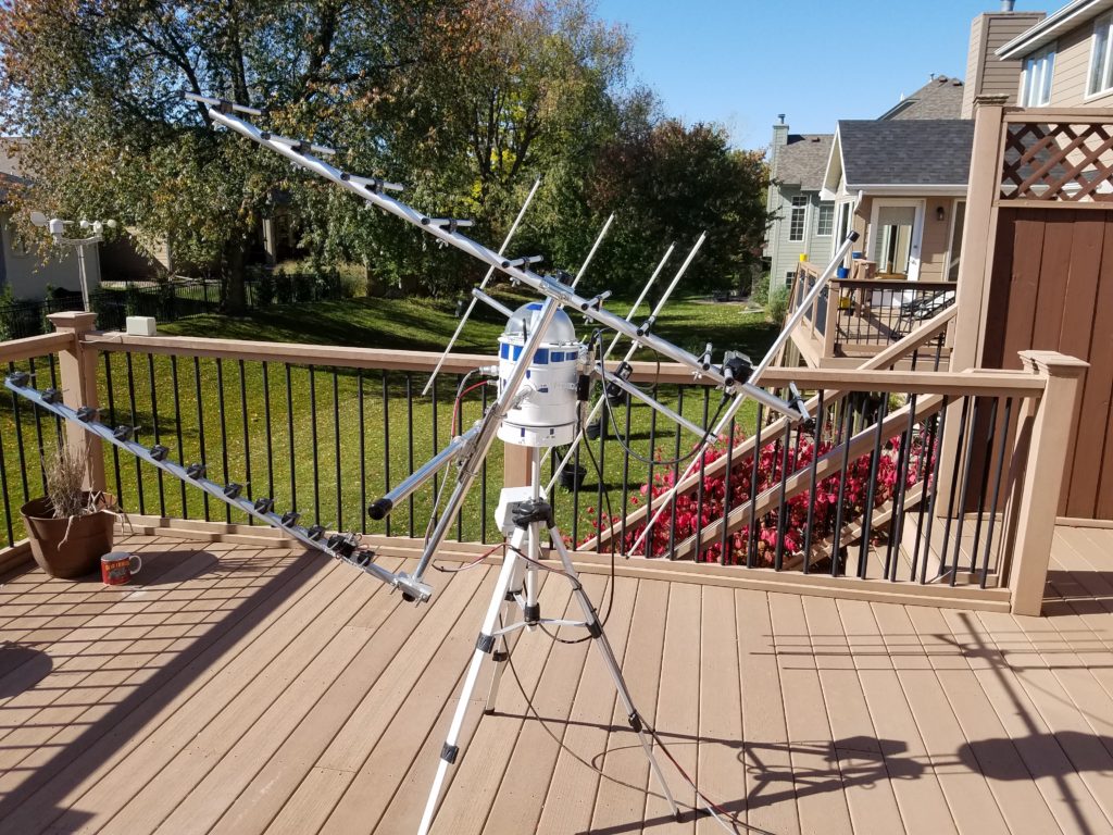
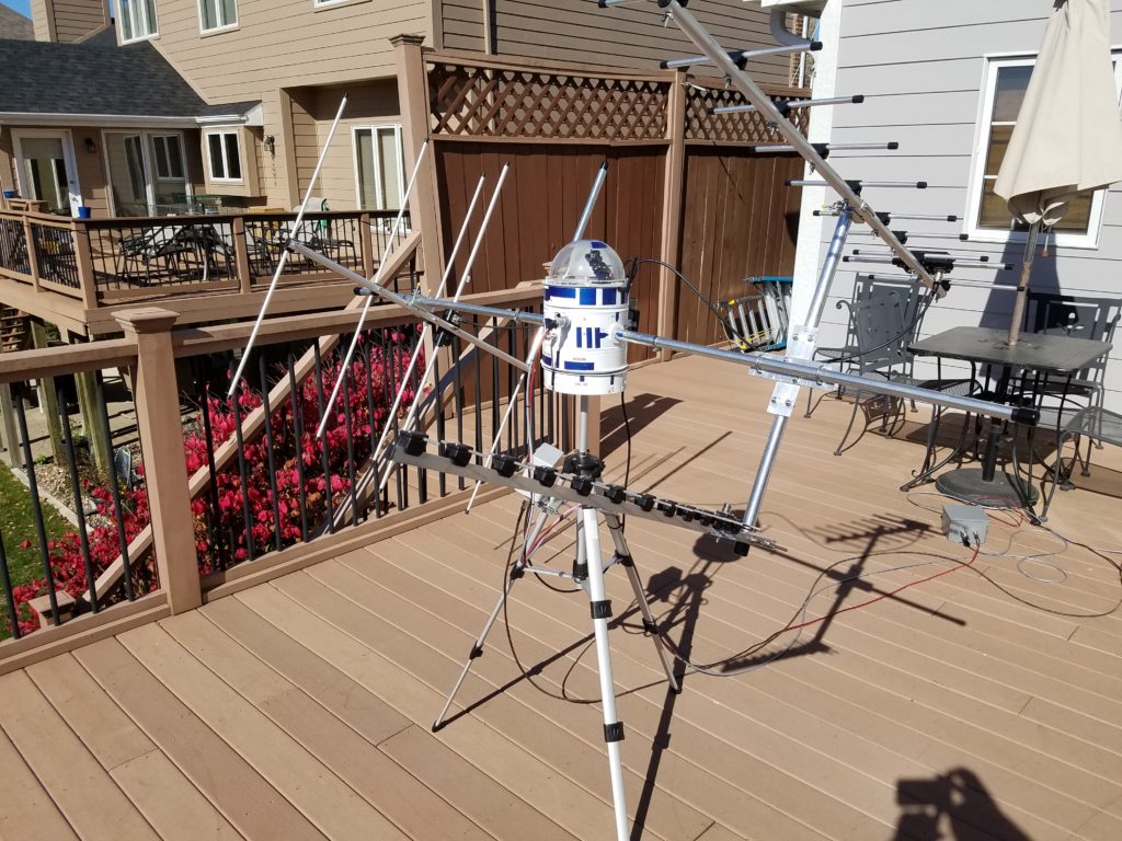
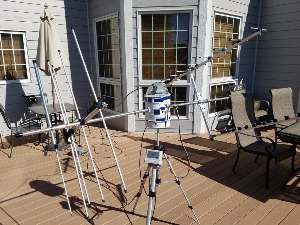
The IC9700 has three power connectors. So, I installed a Diamond MX3000N triplexer to the IC9700 with its attached 12″ connectors. From the triplexer, I’m running approx. 75ft of LMR 240 UltraFlex to an MVV-2000VOX wideband Pre-Amp 2m/70cm/23cm. On its from WIMO in Germany. I know the picture shows the DBA270! (UPDATE 4/2021: Coax is now 75ft(25m) of EcoFlex 15+ and 15ft(3m) of LMR600). This output goes to a Comet CFX-4310C (2M/440/1200MHz Triplexer ), which feeds the three antennae. The antennas for 2m: Diamond A144S5R, and 70cm Diamond A430S10R, and for the newly installed 23cm antenna, I went with the 13el. PA1296-13-1RA. A cross boom bracket was made from 3/8′ aluminum, utilizing 1″ stainless U-bolts to minimize additional weight. There is a 4ft separation between the 70cm and 23cm yagis. Analysis of receiving and transmitting to the antennas is shown in Table 1 & Table 2 below.
From this setup, I’ll see a 25-30dBi receive net gain considering all losses. The Bias-T voltage controlled by the IC-9700 turns off the preamp on transmit. I went with the Diamond 5 element 2m yagi, and the Diamond 10 element 70cm antenna due to the fact they weigh just 1.4 lbs each and will balance the boom. Well, that is all fine and good until you add a 23cm yagi. Note, I have now oriented the 70 & 23 cm yagis to be horizontal. The 2m yagi is left in a vertical position with an added 1″ OD- 24″ tube placed on the reflector. The balance is good, and it’s tracking as it should!
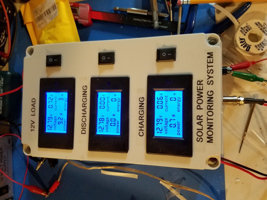
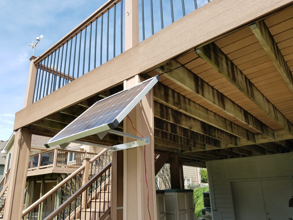
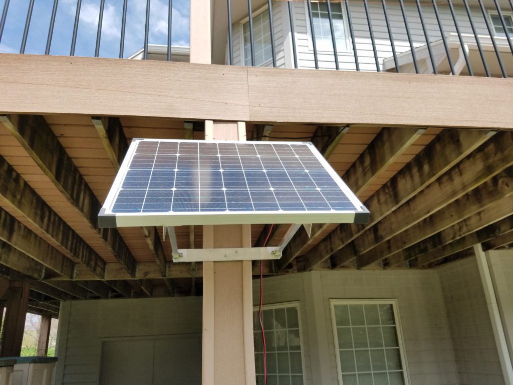
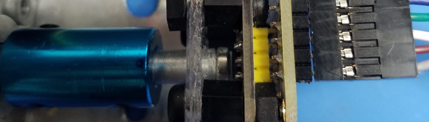
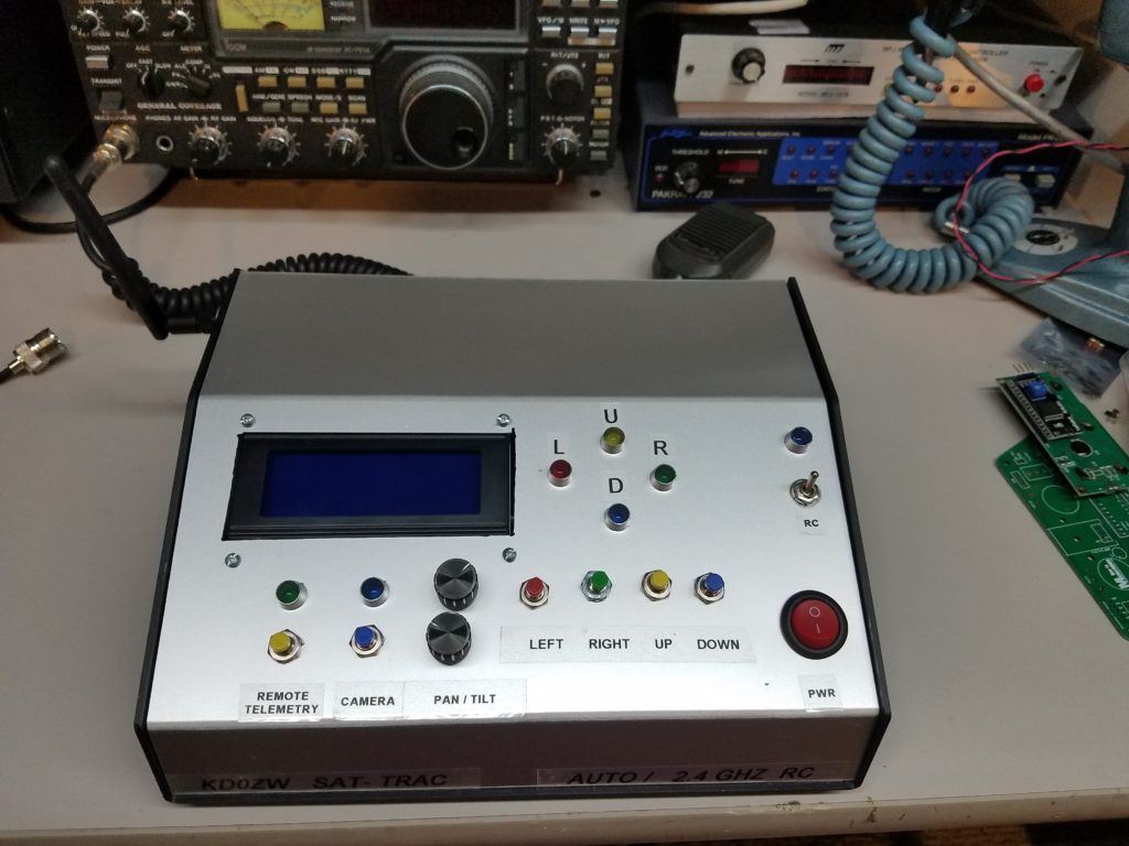
The SAT Trac system is powered by 2 80-watt panels with custom mounts. The power is routed into the power monitoring system, where charge controllers maintain a couple of deep-cycle batteries. The health of the system as well as the proper operation can be seen on the load monitor. The current position of the ZW3 droid and antennas can be seen on the controller as well as from a droid-mounted 5.8ghz FPV camera.
Satellite System Analysis:
My current IC 9700 is set up to transmit power at 100,75 & 10 for 2m,70cm & 23cm respectively: Tables 1 & 2 show the coax upgrade of 75′ (25m) EcoFlex 15+ & 15ft(3m) of LMR600. Using all N-type connectors. Also, the DBA270 dual-band preamp has been swapped out for MVV2000vox. Connector insertion losses are approx. from the work from John S Huggins https://www.hamradio.me/graphs/connectors/UHFConnectorGraphs/Insertion-Loss_S21_1000.png I’ll use insertion losses per N-type at .15dB from 144mhz-1.2ghz per connector.
Table 1. Receiving calculations
| Ant | Ant type | EL | Ant Gain dbi | Pre-Amp dB | 75 FT COAX dB | Gain dBi | Formula: Gain – ( triplexer ins., connector, and preamp insertion (.5dB), losses.) Note: coax loss already considered. |
| ___ | ________ | __ | ________ | MVV2000vox | EcoFlex +15 (25m) LMR600 (3m) | 8 N-type connectors -.15dB each 2 Triplexers @-.3 dB ins. losses each, and ins. loss of preamp =(-1.2dB) +(-.6) +(-.5)= -2.3dB | |
| 2m | A144S5R | 5 | 9.1 | 20 | -.924 | 28.18 | 25.876 |
| 70cm | A430S10R | 10 | 13.1 | 20 | -1.624 | 31.48 | 29.176 |
| 23cm | PA1296131RA | 13 | 15.6 | 20 | -3.164 | 32.44 | 30.136 |
Table 1 shows that if we use a masthead preamp, high gain antennas, and high-grade coaxial cable, and limit the connectors and insertion losses to a minimum, we will achieve a better signal to noise from the satellite.
Table 2. Transmitting calculations
| Ant | Ant type | EL | Ant Gain | coax losses dB 92ft | connector & Ins. losses dB | Watts to Ant | Net Gain dB | EIRP/Wts |
| 2m | A144S5R | 5 | 9.1 dbi | -.924 | -2.3 | 47.59 | 5.876 | 55.88/386 |
| 70cm | A430S10R | 10 | 13.1 dbi | -1.624 | -2.3 | 30.38 | 9.176 | 57.93/621 |
| 23cm | PA1296131RA | 13 | 15.6 dbi | -3.164 | -2.3 | 2.84 | 10.136 | 50.14/104 |
Looking at Table 2. we can see how losses reduce the total watts to the antenna. According to TMS, the LMR600 ultra flex will be approximately 81% efficient at 2 meters, 65% at 70cms, and 46% at 23cm, to the antennas at 92ft (28m). So even high-quality coax will leak or attenuate the signal at a reasonable distance. The best bet will be to use a vox masthead preamp, keep your coax run as short as possible, use the best coax you can afford, and limit the number of connectors used. And, use only N-type for satellite work.
There you have it… To work them, you have to hear them. So, efficiency from and to the antenna as well as the performance of the antenna itself tells the tale. And finally, use a masthead preamp to overcome the inherent losses!