Upgrade to ZW3 — 8bit to 32bit & 1/4″ chain drive!
Here we go… If making an accurate satellite tracker is not hard enough, I have to reinvent the wheel. You see, my first version using 3D aluminum gears and belts failed, the second version doubled up the gears and belts and worked well until it gets below 32F 0C and the belts lose their flexibility and grip. So, version 3, removes the belt drive system and makes way for a 1/4″ chain drive. Clearances, different gear ratios, programming, and fabrication will be needed. This is ZW3, the KD0ZW SAT-TRAC auto trac, or manual 2.4 RC controlled tracker. With a 5.9Ghz camera. As an AMSAT member, I use the SATPC32 software and made the controller control the droid, affectionately known as ZW3. As I work thru this project, started in January 2019, I will hopefully be happy with all of the upgrades going forward. Such as an AS5600 IC hall effect magnet super-accurate positioning, heated inside controlled with BMP280 sensor, 1/4″ chain drive, the 32-bit controller the 32bit ZW3 control head, and the fan venting when it goes over 100F here. Think I’ll stop there? No way, I still need to load up the boom with dual 70cm RHCP/vertical capabilities and pump up the 23cm volume. Whoaaazzz I better get busy.
#1 Fabricate the bracket 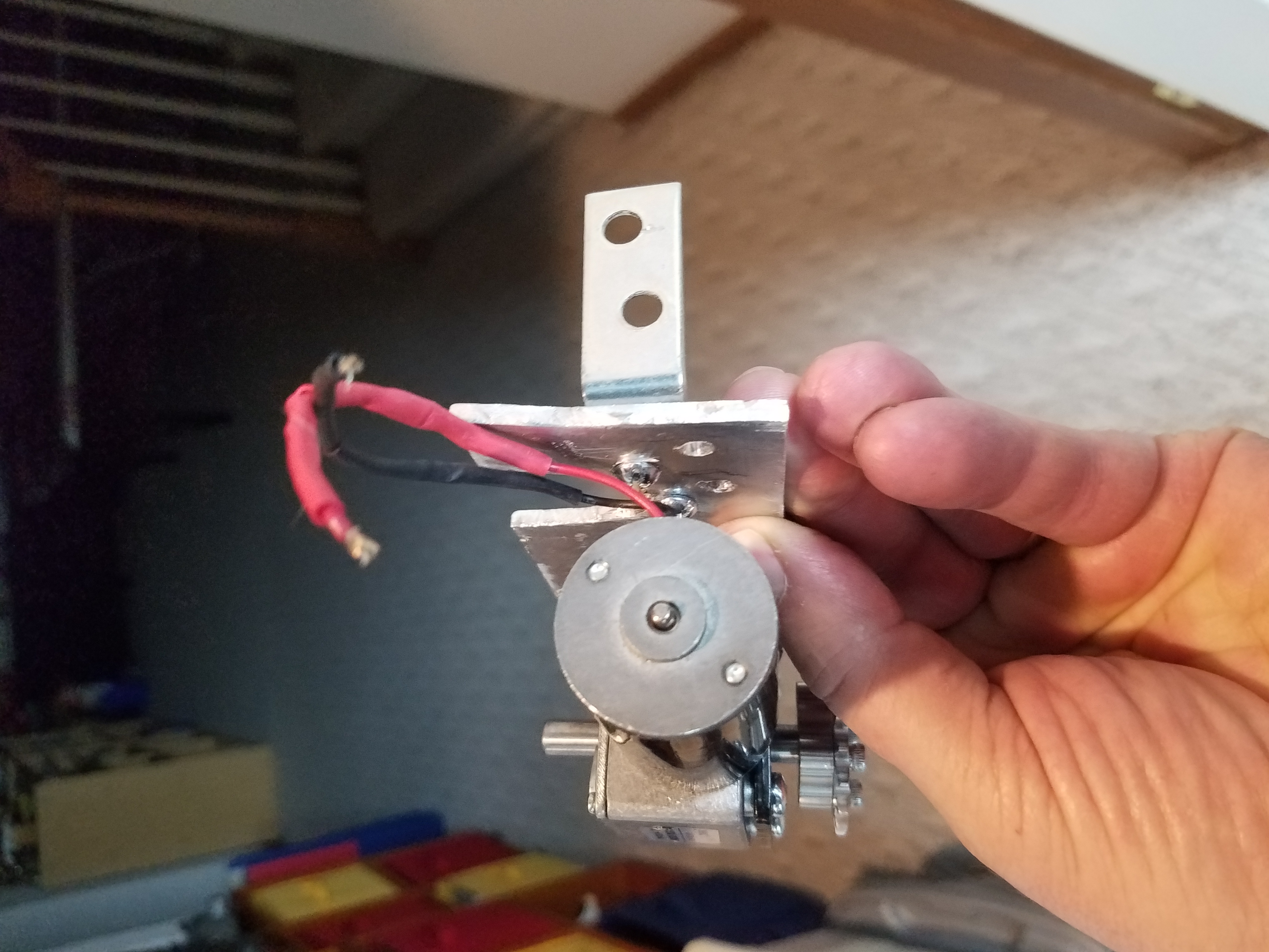
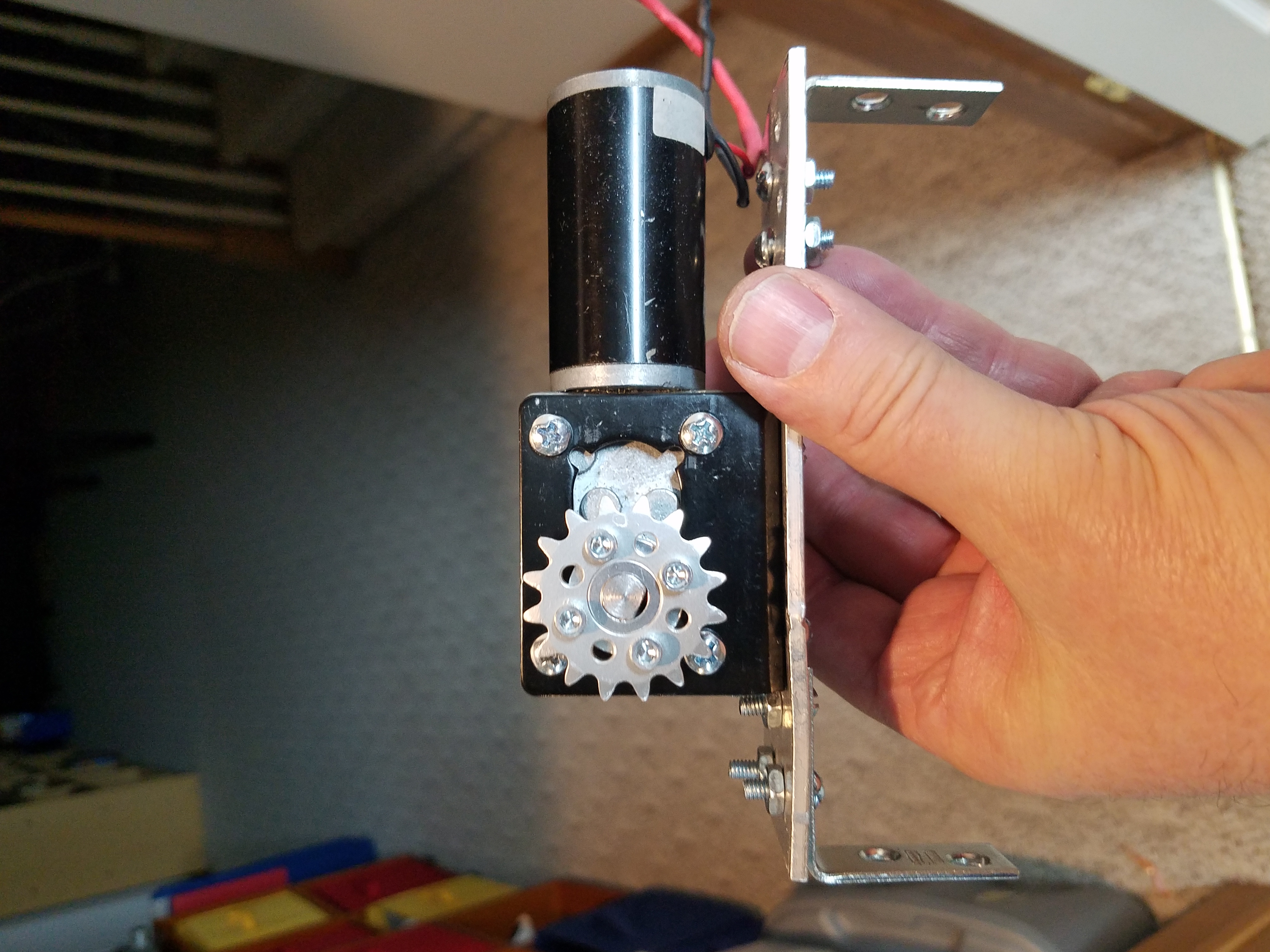
# 2 side view with L- bracket attached 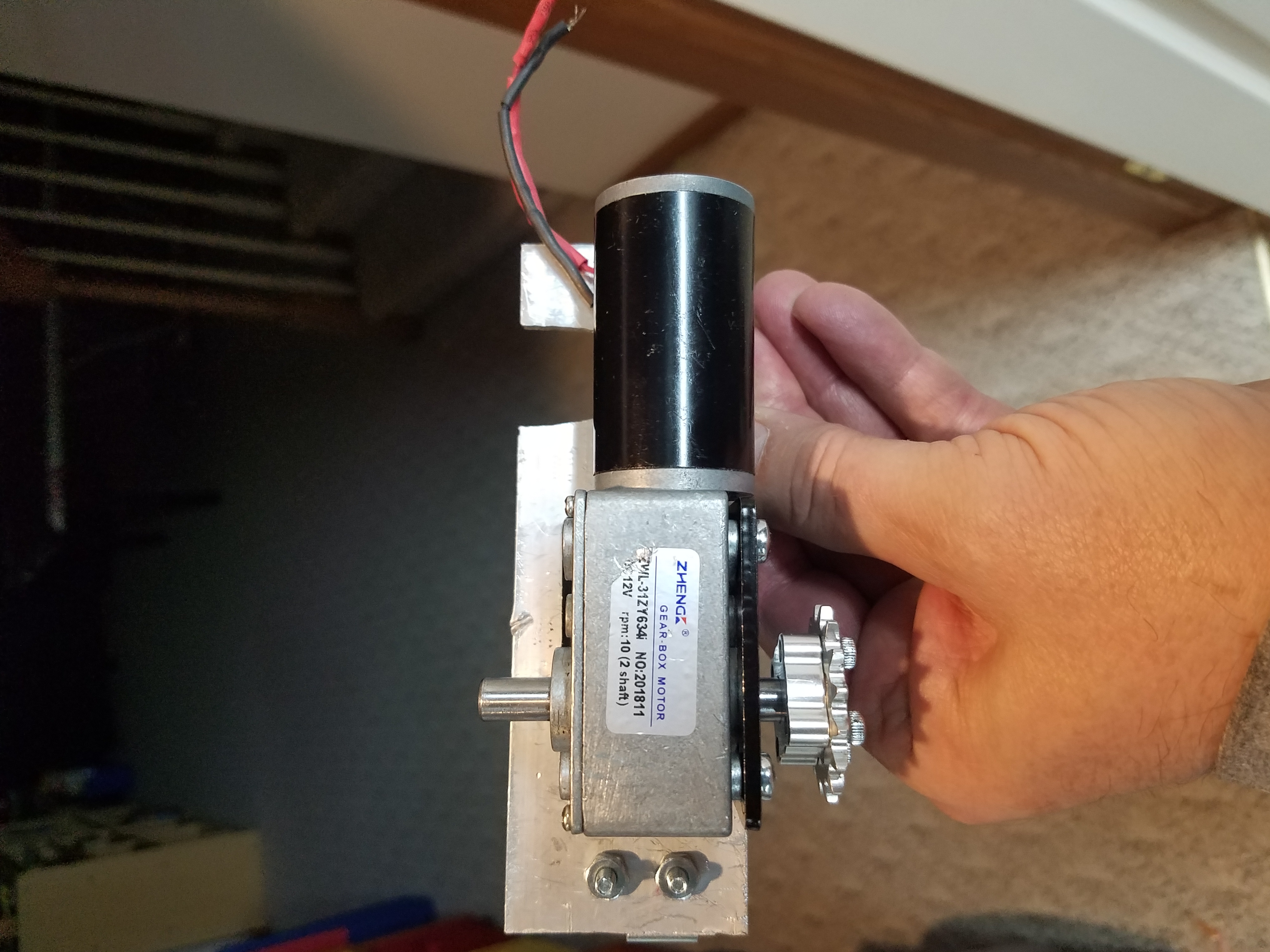
# 3 Back view of dual axle motor 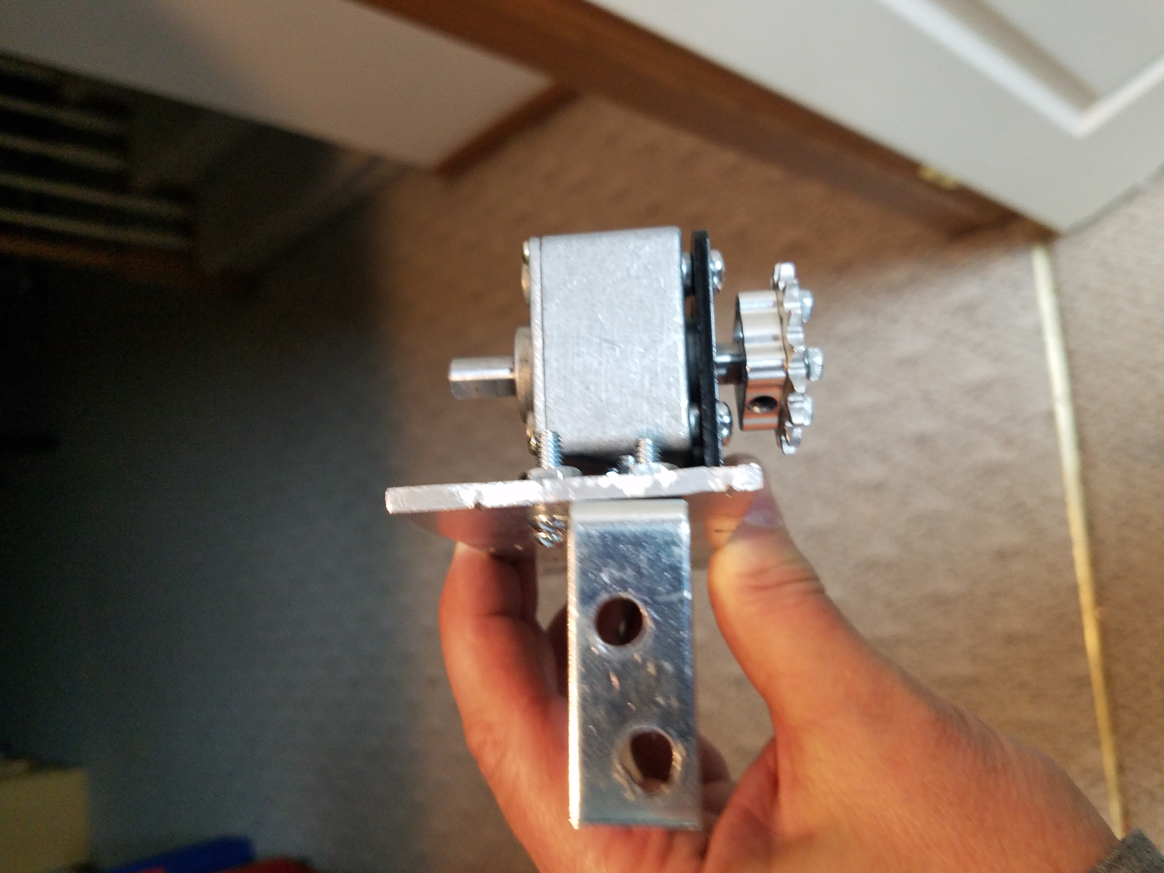
# 4 side view 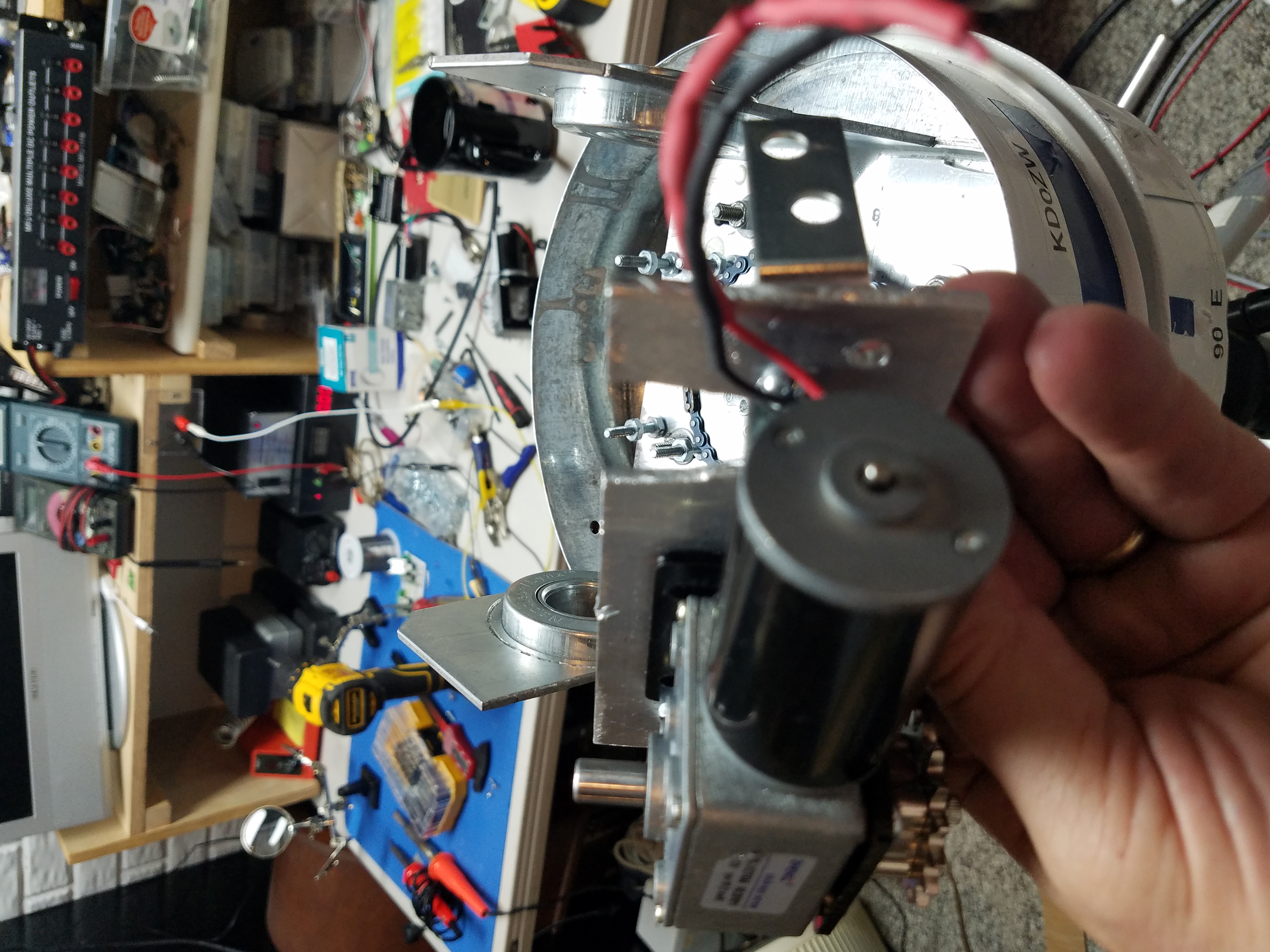
# 5 The AZ plate had to be notched to accommodate the 40 tooth Elevator gear 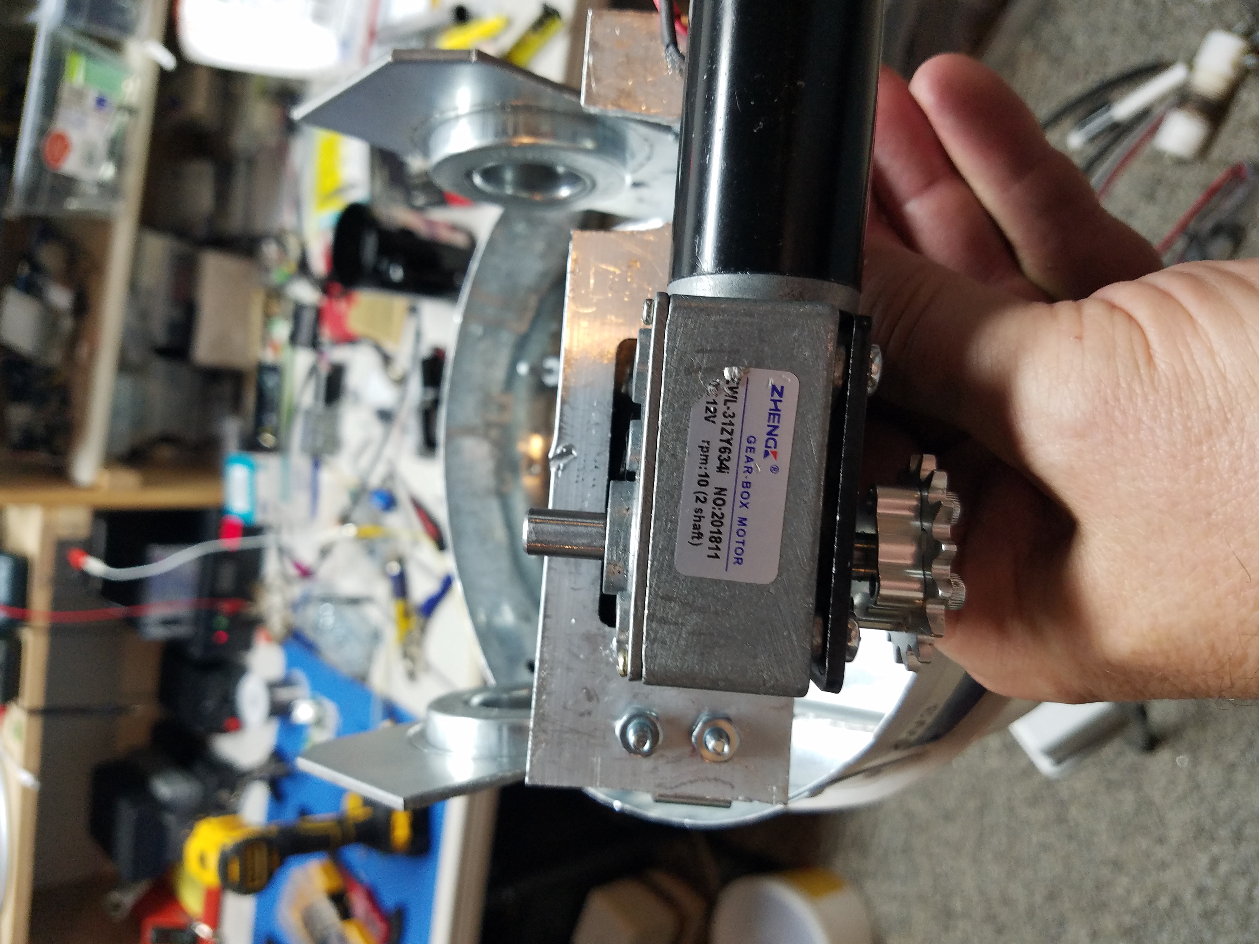
#6 another view
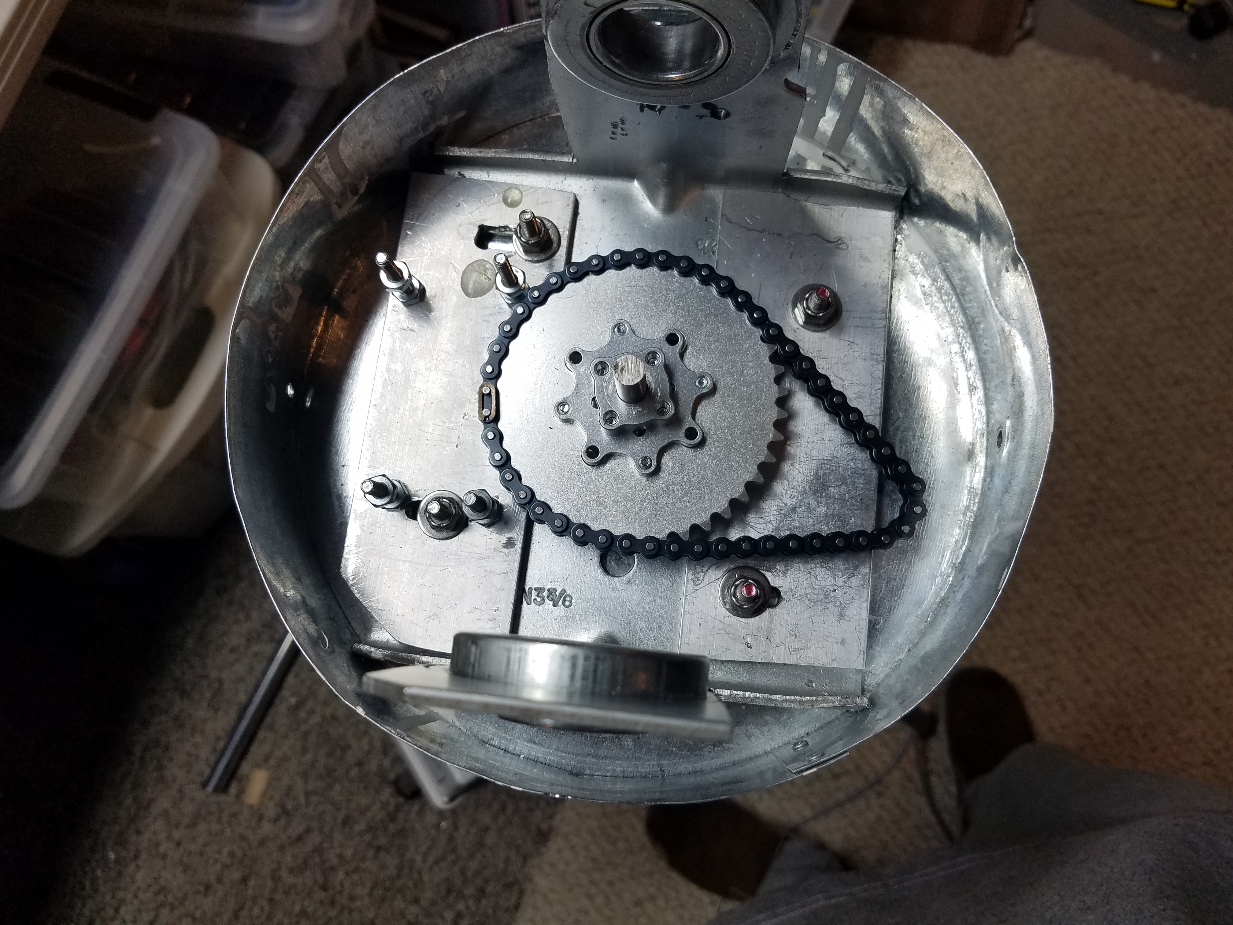
#1 Naked ZW3 from Top 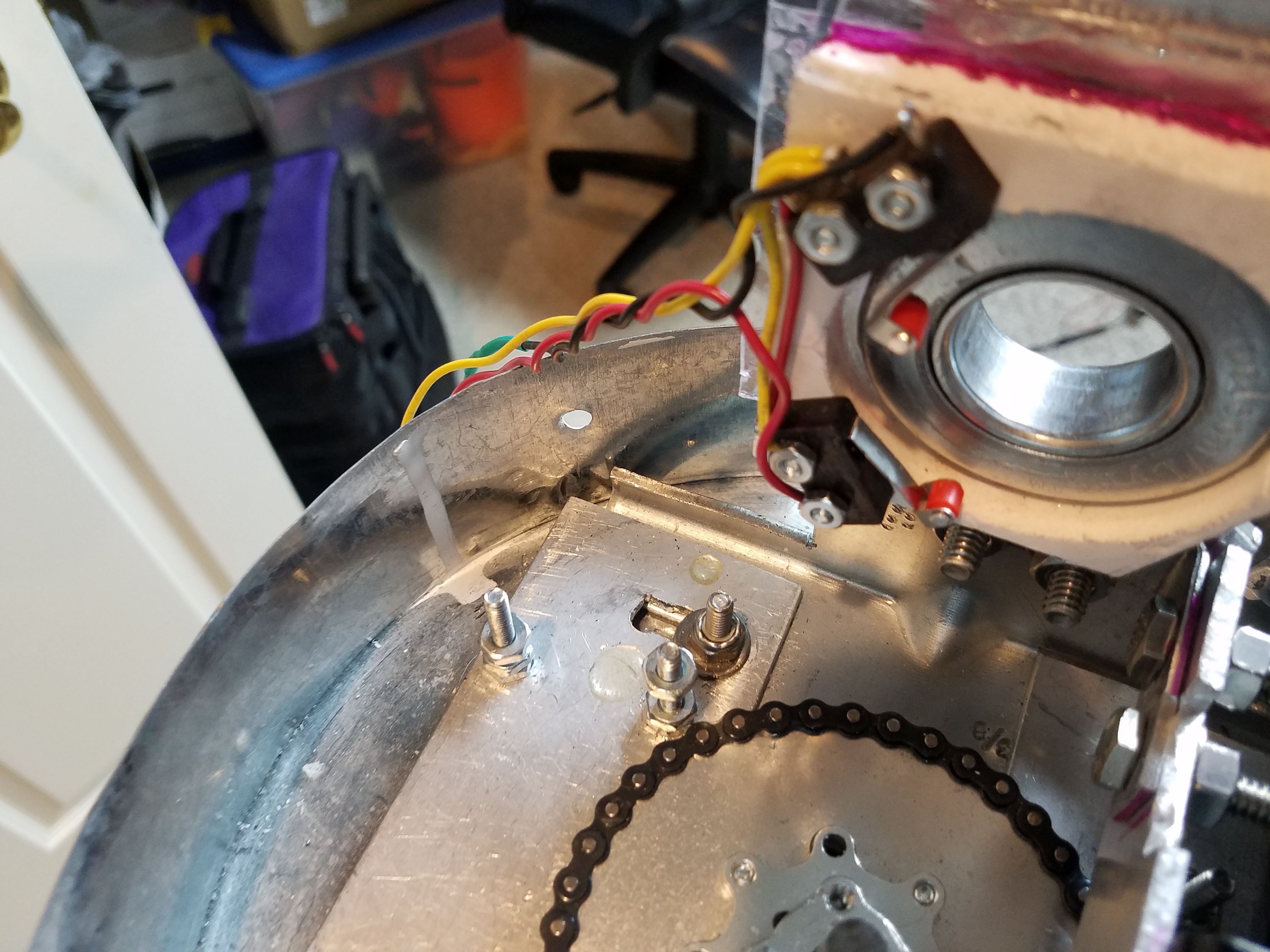
#2 View of EOT switches 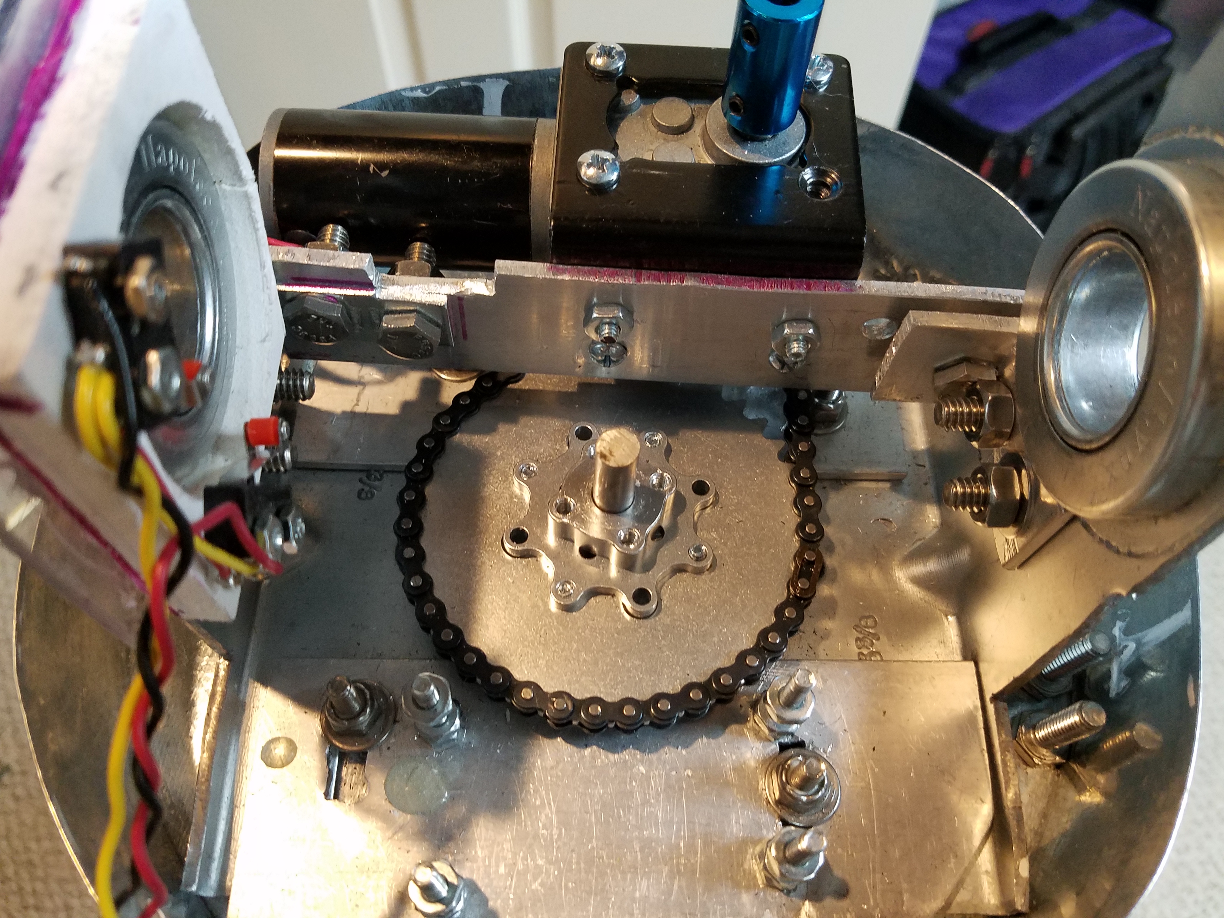
#3 AZ mounted!
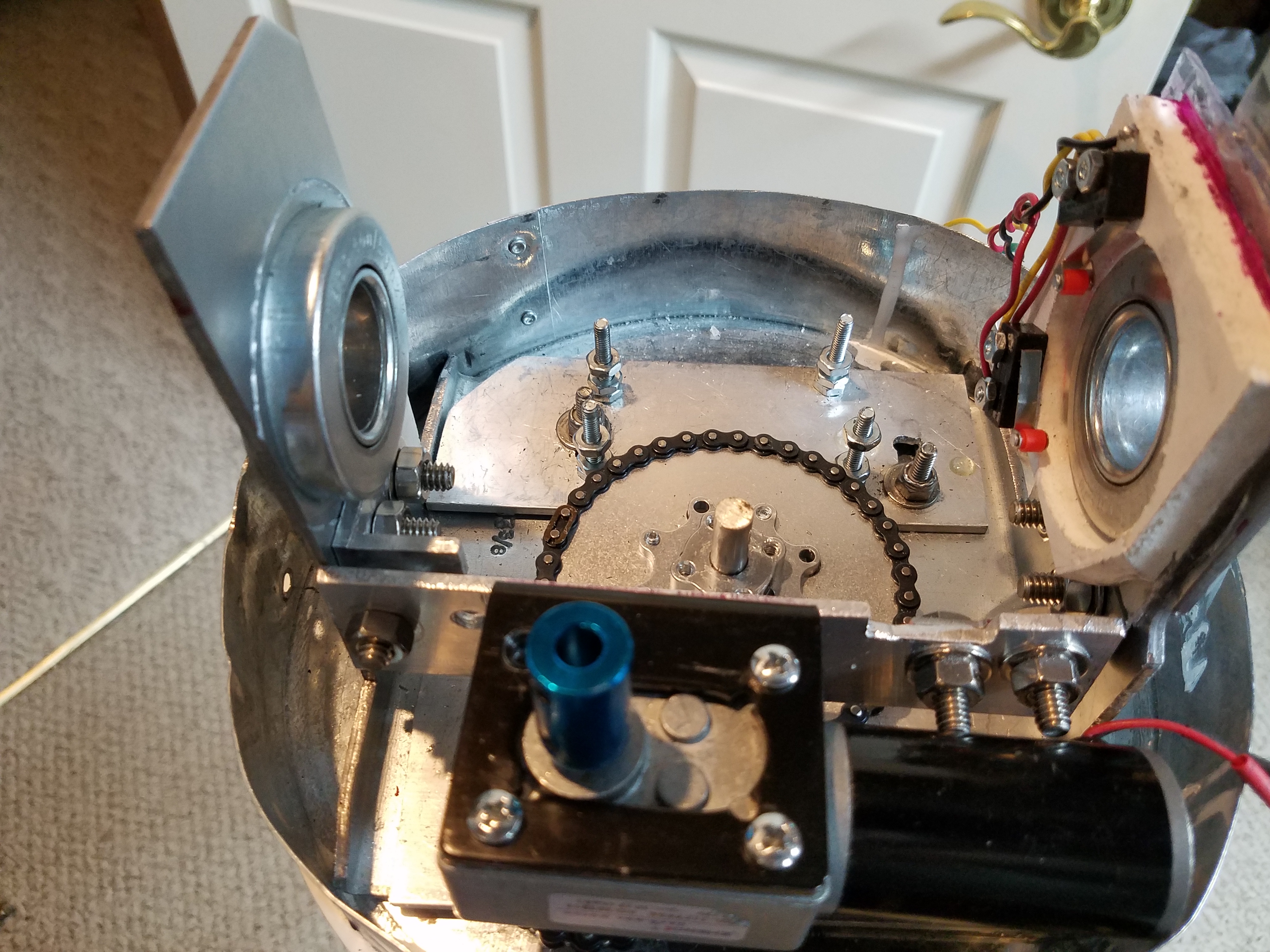
#1 AZ with adapter for precision pot 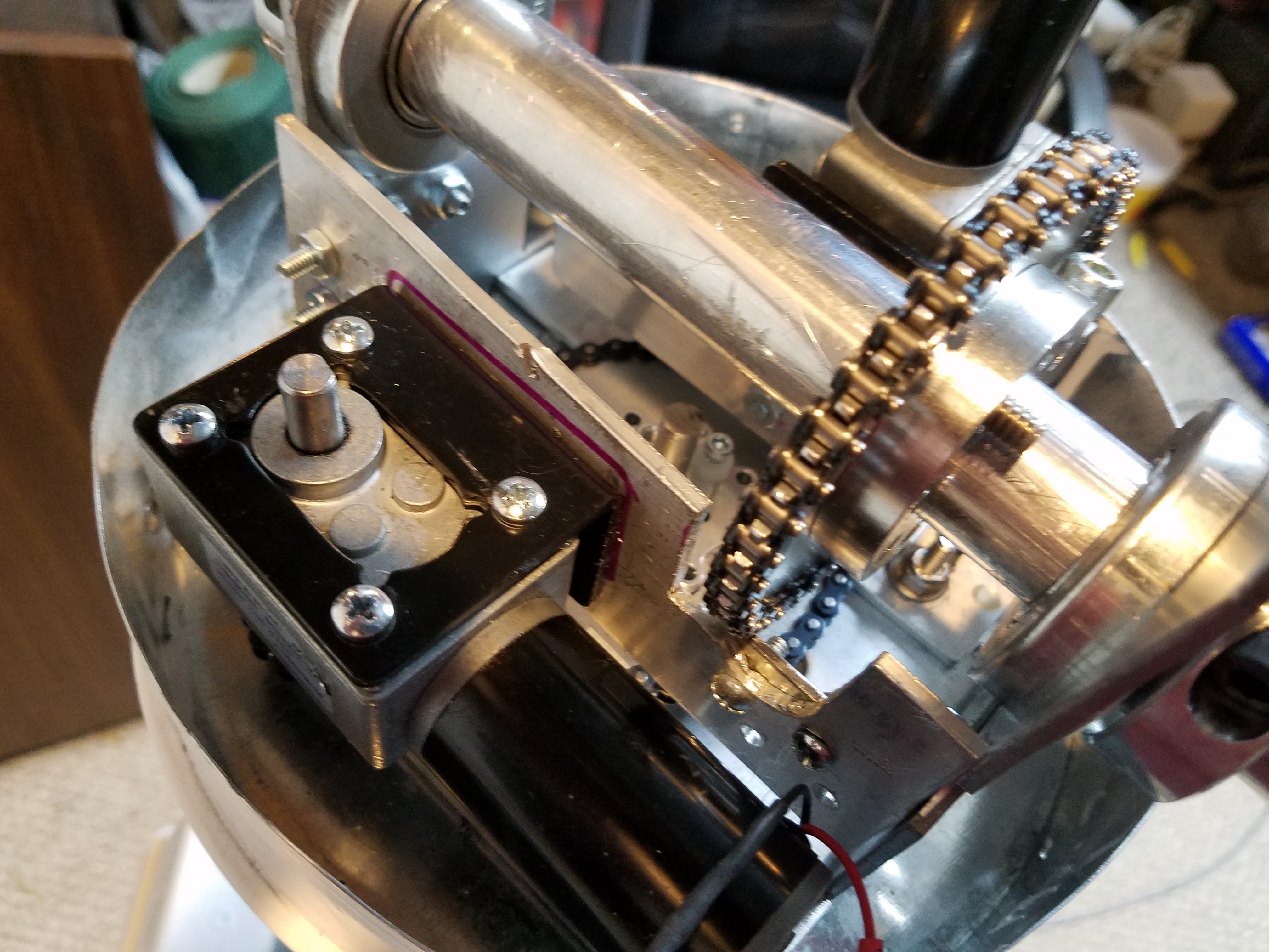
# 2 Elevator gear installed and checked for clearance
Not a lot of room for error, the motor sits horizontally. It is a dual axle motor so I use an 8mm to 6.35mm adapter (blue) to connect to the precision potentiometer. This works out very well as the pot will be mounted so we don’t put any stress on it. I’m using 10k pots that functional to -40F. Note: should you be using 0 degree rated pots, you will find when it’s really cold, your off from room temperature. In my case, I found 70F- outside temp was the degrees I was off Azimuth and Elevation. Funny how that worked out. I’m currently working on fabricating an upgrade to the system to use the AS5600 IC and small diametric magnets for super 12bit positional accuracy. This is a work in progress with my 32-bit upgrade from this 8bit Mega2560 board I’m currently using.
#1 AZ tested and working 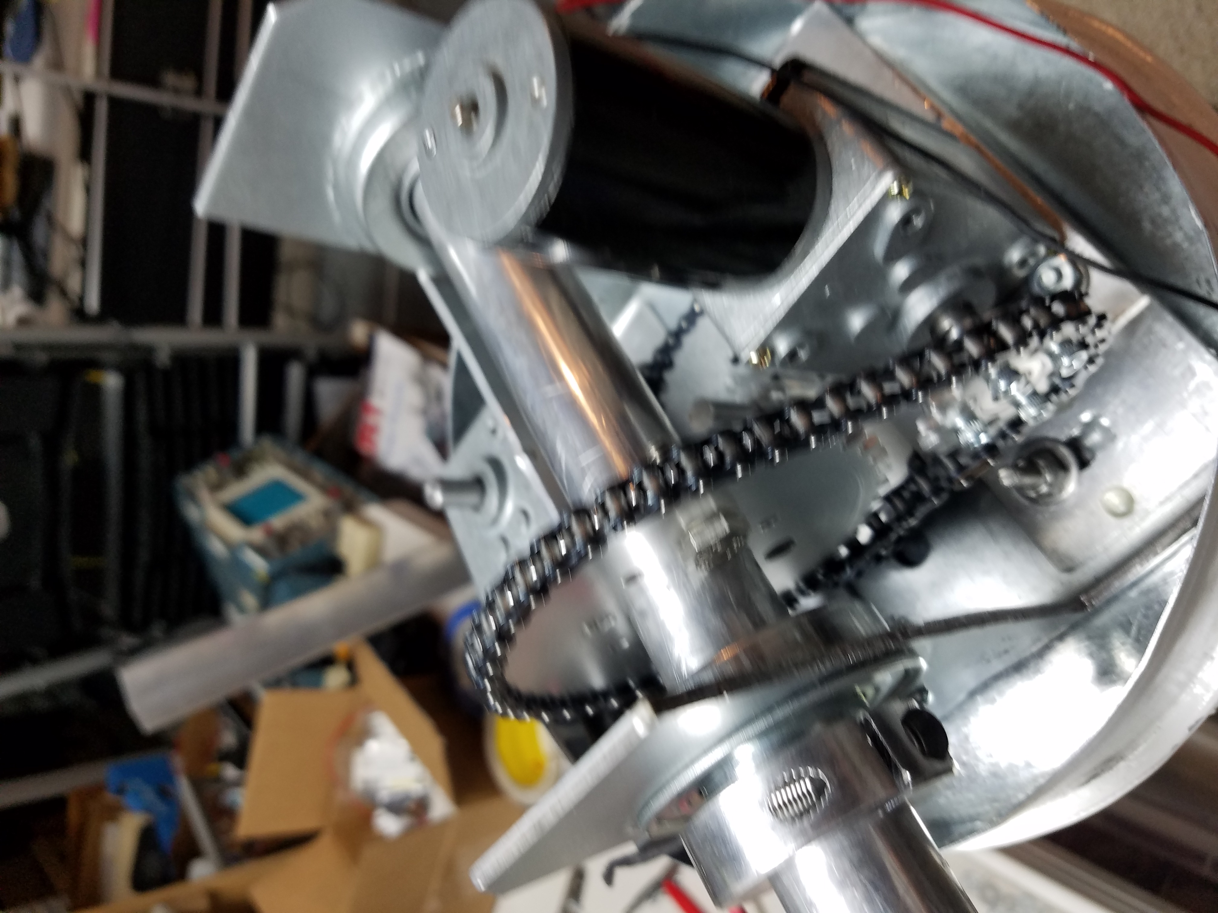
#2 Elevator motor is mounted and gear positioned 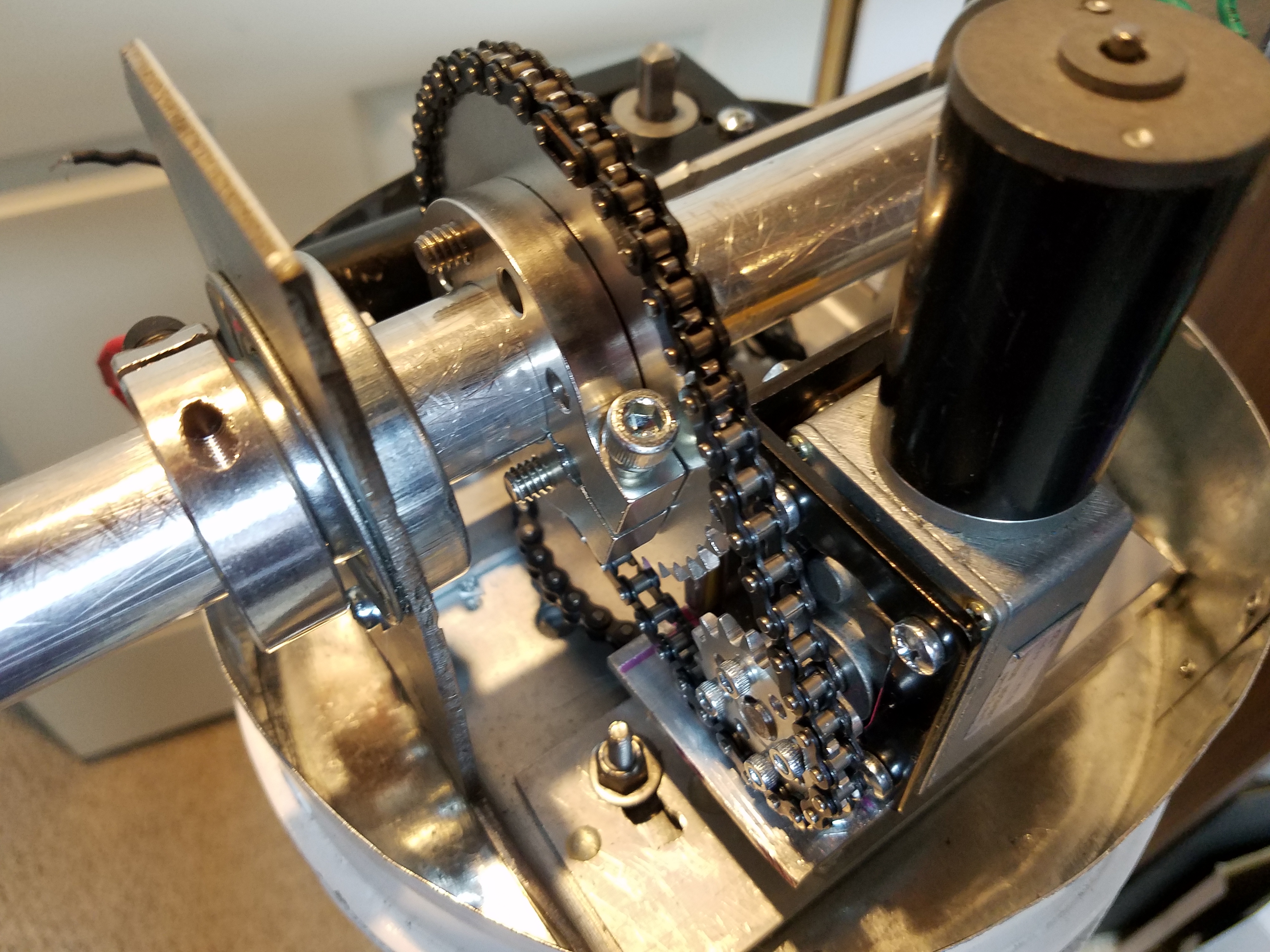
#3 Elevator system is aligned and working smoothly 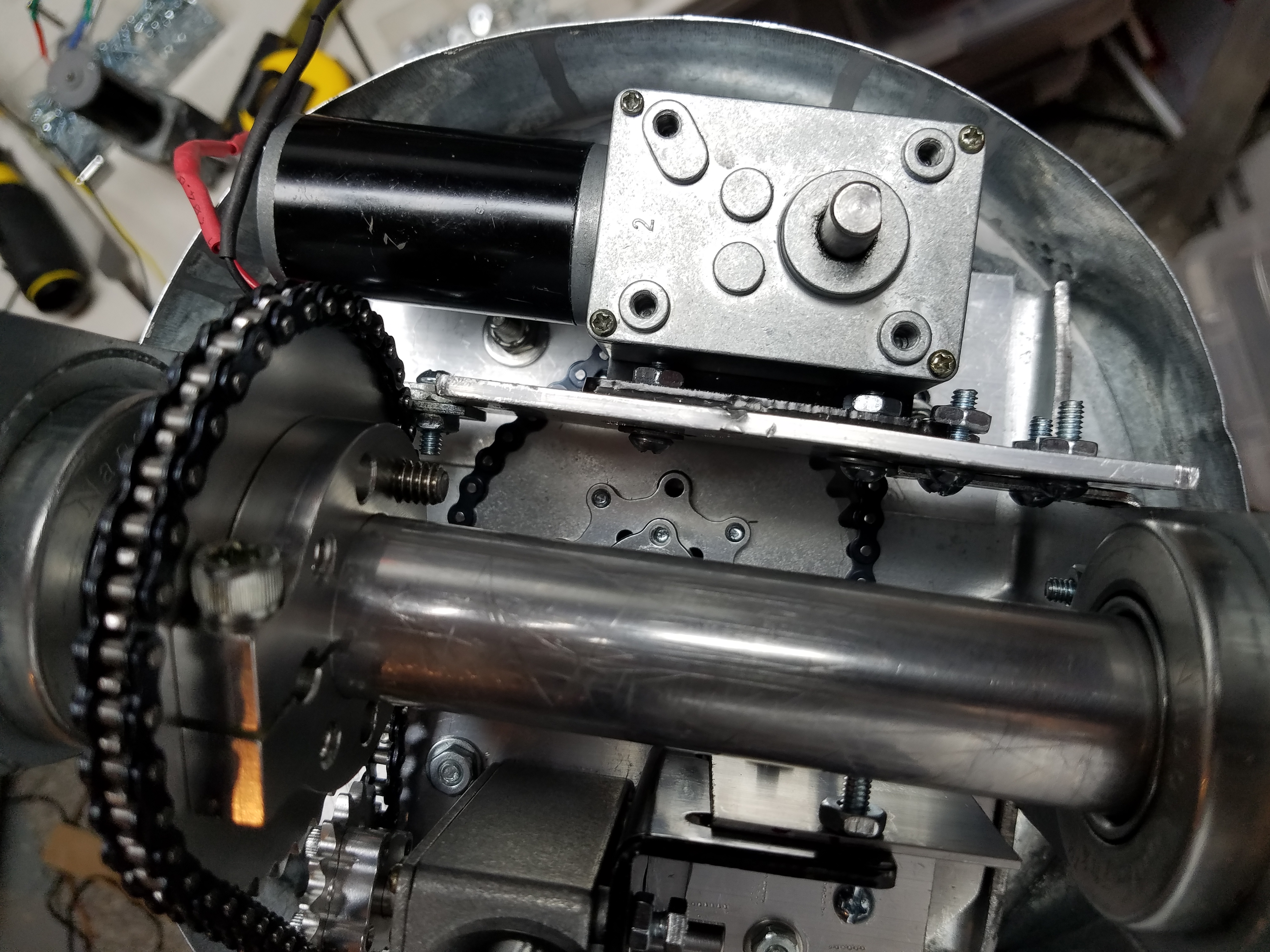
#4 Hardware is in there and not rubbing on anything… However, I was getting a little movement under power so I replaced the #8 bolts in this picture with 1/4″ stainless steel bolts… big improvement. You can torque them down without stripping them.
Here we test it out to see if it runs smooth and pulls a consistant current.
Okay, we’re happy with the chain drive, so I put it back together and added some new enhanced antenna configurations.
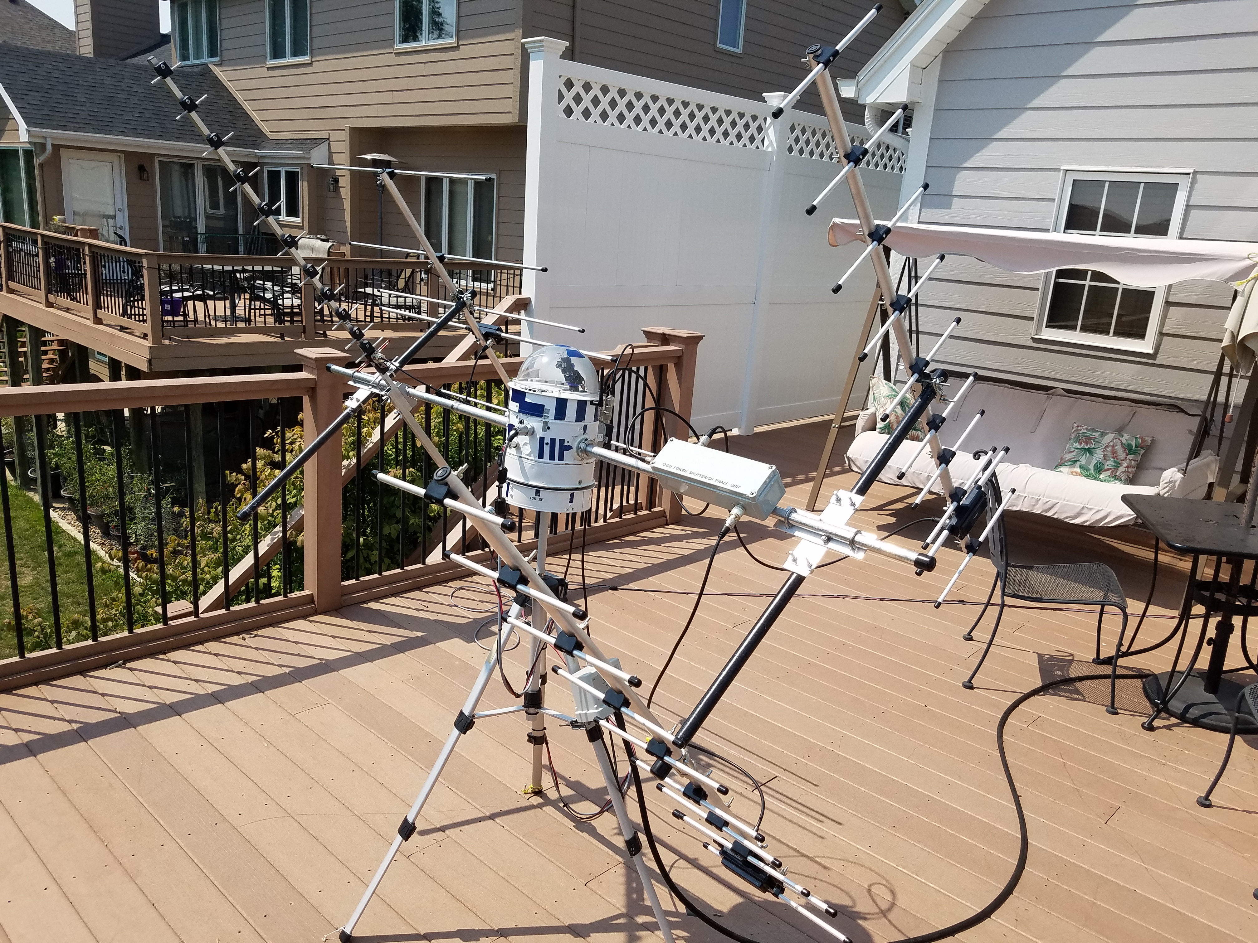
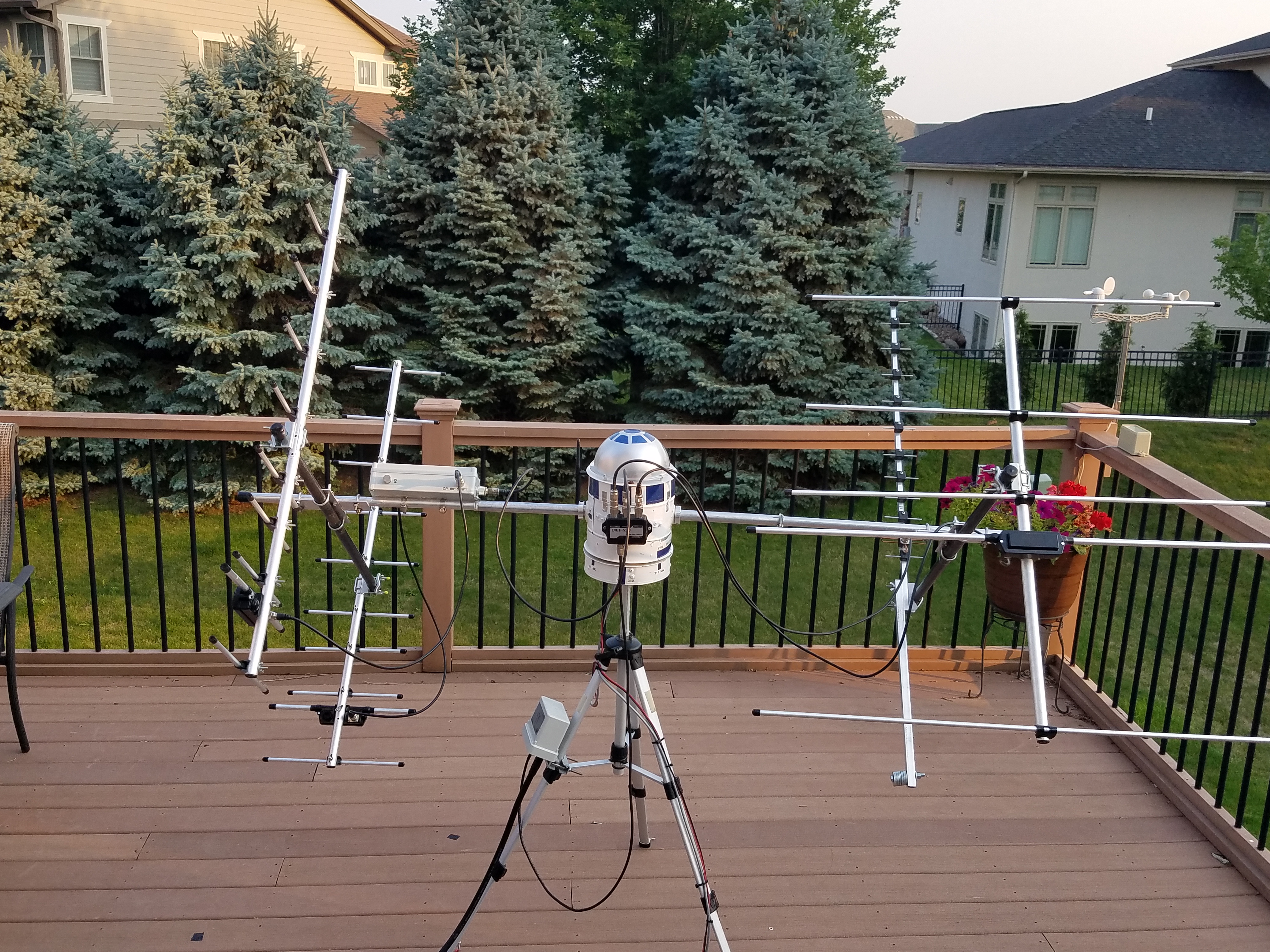
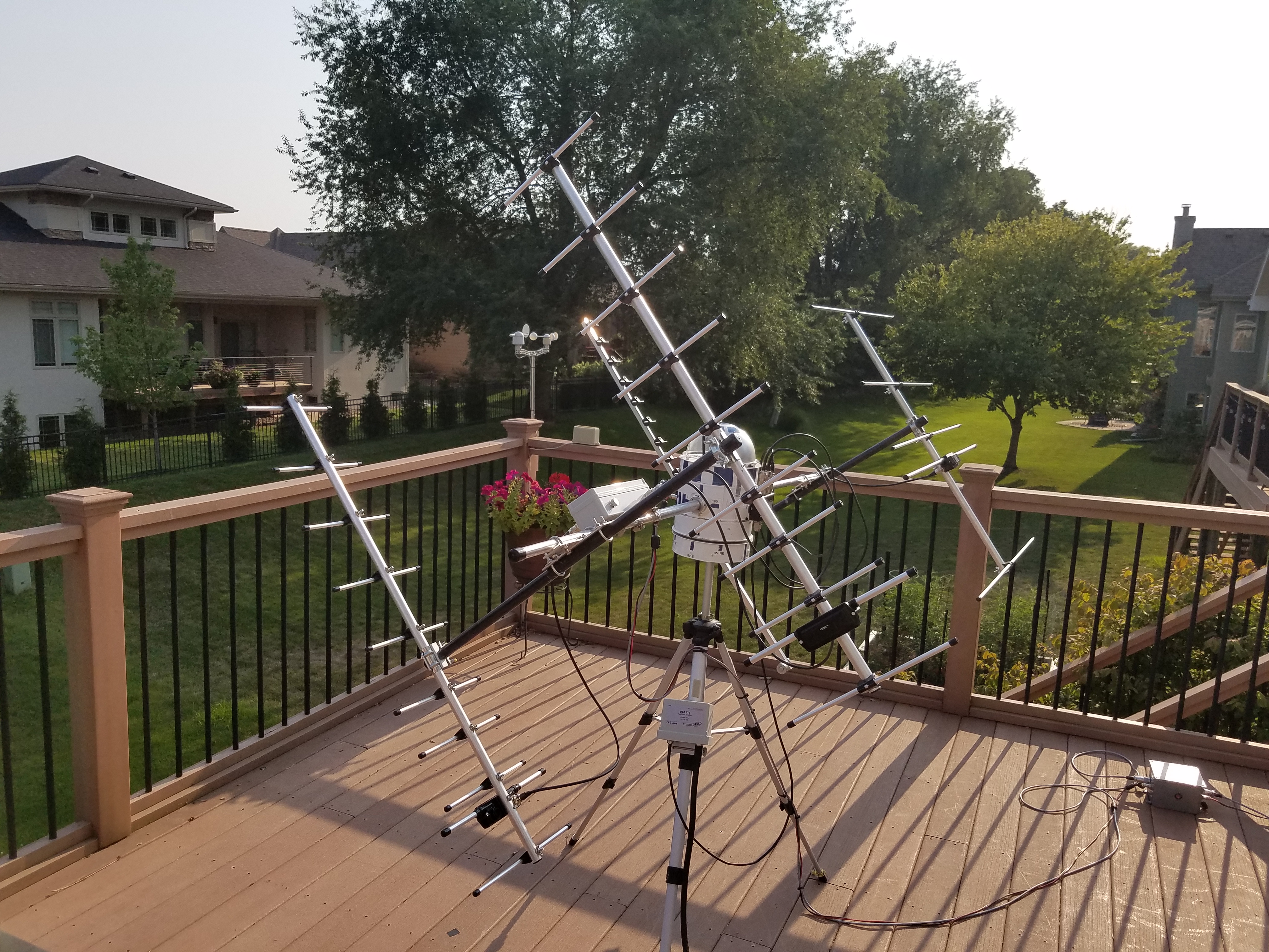
Well, originally ZW3 was configured with 2 vertically positioned antennas for U/V & V/U satellite work. Over 600 contacts were made when the belt drives were replaced with 1/4″ chain drives. Why? Well, the rubber belts were not handling the extreme cold, high humidity, and weight from 4 antennas. So, It was re-engineered with aluminum gears and chain drive. How does it work? Love’n it. It can spin the array 360 degrees in 38 seconds. With no braking, this will be hard on the unit in the long run. So, 70 seconds or a little UNDER 1 rpm was chosen to have, sufficient torque, speed, and accuracy to chase birds. It moves smoothly and holds positions in the X, Y, Z positions.
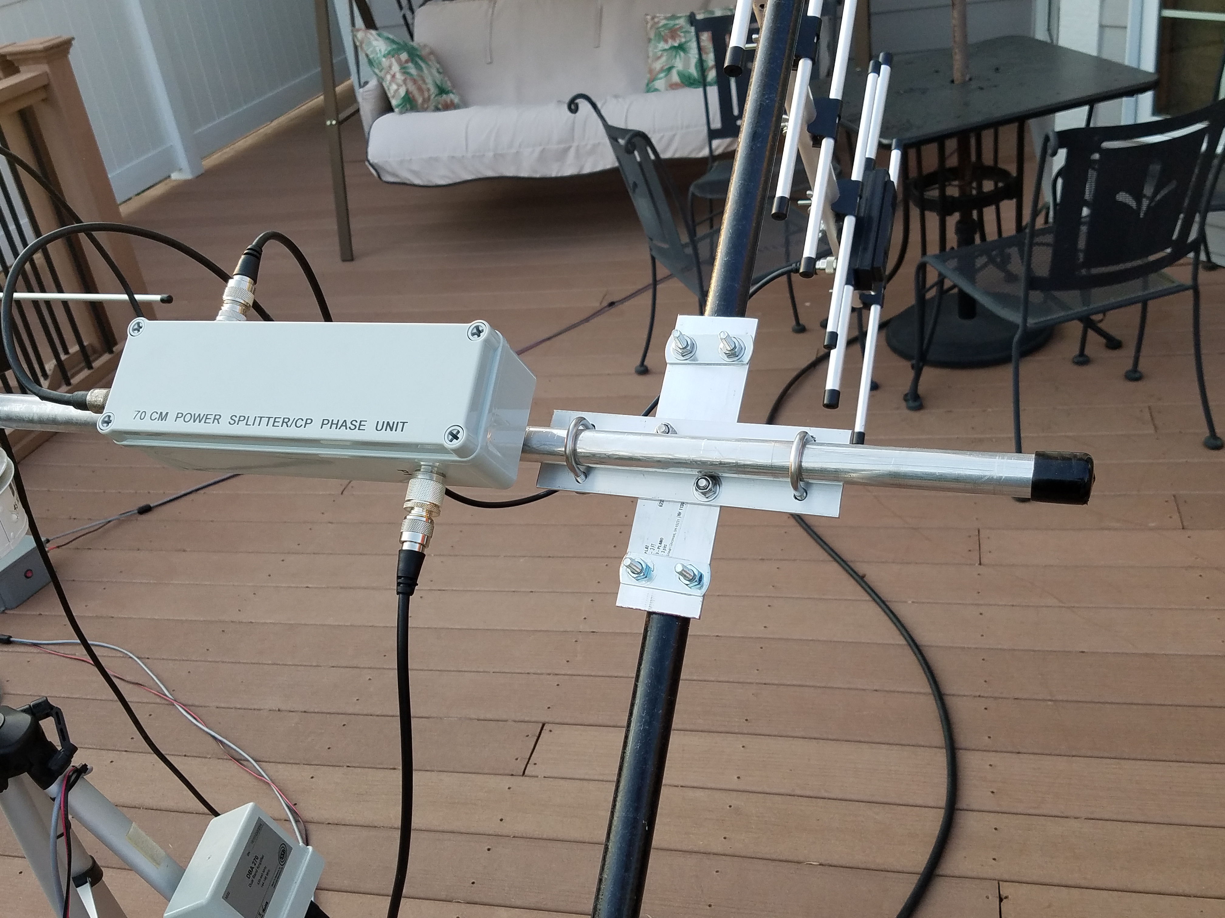
Observations with 70cm RHCP:
Going from a single 10 element 13dbi yagi to two 10 element yagis with a power splitter/phase unit to achieve RHCP is an interesting change. According to Mak SV1BSX (April 2006) I could experience a -3db signal loss when I receive a signal from a Vertical or Horizon polarized satellite. Most of the sats are spinning, so getting a true Vertical or Horizontal signal is unlikely. An RHCP signal from the satellite will give me the least attenuation or 0 Db loss. My challenge will be receiving LHCP signals when I can expect a -30db loss. Wowzaa, that’s a deep fade. This is why some hams have a switch to go from RHCP to LHCP and back again.
So, what have I seen? Well, the RHCP 70cm uplink is giving me a steady downlink to my vertical polarized 2m antenna. Using the IC9700, I can watch my downlink S-meter when I transmit. I’m also able to hit the bird at a lower elevation. When using the RHCP 70cm antenna for the downlink, I’ve noticed the ability to hear those weak rovers at the edge of mine and their pass. For example, WL7T, “Tyler”, was operating a rove from BQ50… yeah BQ50… He must of either parachuted in or got there by plane…Anywho, He was calling CQ Sat WL7 “Tangoooooo” BQ50 on 145.950 RS-44… What? That sat was over the middle of CA, and at my location EN31, I was seeing a 290 AZ by 13-degree elevation. I usually look for a 20+ elevation before I transmit. But hey, it’s Tyler, and he’s at the top of AK! I better give him a call quickly. So I did, and he immediately called me back… His downlink to my RHCP was 1-2 s units or approx. 5-10dB above my noise level. When working satellites, that is a 100% copy signal. At my station, a very strong station is 10-20db or 2-4 s-units above the noise… You own that sat and I need to turn down the audio…lol So not only did my vertical polarized 5 elements 2m yagi reach the bird, but the received downlink was superb. Wow, what fun.
In closing this adventure, for now, I need to give you more information. First, I’m using yagi’s for 2m and 70cm with a gain of 9dbi to 13dbi respectively. You see, giving a signal report or R-S as a 5-9 when working satellites is a problem. Here is what I see on my S-meter. If I turn off my masthead preamp, and radio pre-amp off, I hear nothing with a noise level of S=0 to 1. Turning on the IC9700 pre-amp, I see S=4 to 5 or about a 20db signal boost. Suitable to work some satellite stations, but the roves would be difficult. Now, putting on the masthead pre-amp and signals and noise jump another 20db. Noise is now S-8/9. So like I said previously, 1 to 4 S-units or 5-20db above the noise can be solid contact. In summary, a Signal to noise or SN of 5-20db is workable for my station.
10/1/2021 Update on going from an 8bit Arduino to the 32bit Due Arduino Controller and remote:
Well, the addition of a 1/4″ chain drive for AZ and EL and, adding RHCP has worked well. Now, I’ve been working on the upgraded system, and here is a couple of pics of it on the bench.
To view progress on the new KD0ZW SAT-Trac 32 controller and remote (‘ZW3’) click here:
Back to Home