SAT-TRAC – Part 8 Final Testing…
In part 7, everything was going to plan… except the end of travel (EOT) rocker switch for the azimuth was engaging at -5 degrees on the low side and about 340 degrees on the high side. That’s a problem with the satellite is at 345 to 360 degrees or due north of you. When you prototype, you, are always looking for creative ways to solve a problem. Okay, I could just hit it with a sledgehammer and the problem is solved, however, the ultimate goal of creating a working Sat Tracker is not reached… better shelve that creative idea. Well, back a the earlier part of the year, when I was busy building the remote boards, I came up with a couple of industrial-strength rocker switches, and a Q1 & Q2 (2N3904)/FET flip flop circuit to alternated the power on for FET1 or FET2 but not on the same time. How was I going to use this…? Turns out the end of travel (EOT) needs to work perfectly to keep the azimuth and the elevation mechanisms safe. Going rogue in either direction could damage the system… The flip flop motor controller could make it work. So when we go less than 0 degrees or greater than 340 the azimuth(AZ) rocker switch goes HIGH and is noted with an attached interrupt (AZEOT=1). Then the analog input from the precision azimuth potentiometer (A0) could be compared <-30 Deg (275 10bit A0 signal) or > 390 Deg (620 10bit A0 signal)? So here is how the flip flop circuit would be coded. A little Arduino C coming at you…
/////////////// Set-up parms for AZ & EL EOT
volatile int AZEOT = 0;
// volatile int ELEOT = 0;
int AZRlimit = 620;// A0 upper limit in degrees 390
int AZLlimit = 275;// A0 lower limit in degrees -30
int ELUPlimit = 525;// A1 upper limit in degrees 130
int ELDWNlimit = 400;// Down -30 Deg for Switch top 400
int pRelayMS=28; // toggle FET1 & FET2 from pin 28.
void setup(void) {
attachInterrupt(4,azISR, RISING); }
void loop(void)
{
//Use interrupt here and check limits for AZ no Interrupt on EL. EL uses software and hard stop rocker switch!
if ((AZEOT=1) && (analogRead(A0)< (AZLlimit))) {
digitalWrite(pRelayMS, HIGH);
}
if ((AZEOT=1) && (analogRead(A0)> (AZRlimit))) {
digitalWrite(pRelayMS, HIGH);
}
if (analogRead(A1) > ELUPlimit) {
digitalWrite(pRelayMS, HIGH);
}
if (analogRead(A1) < ELDWNlimit) {
digitalWrite(pRelayMS, HIGH);
}
//Interrupt routine for AZ set AZEOT when rocker switch is pushed.
void azISR(){
AZEOT=!AZEOT;
}
}
In summary, when pRelayMS (project Relay Motors and Speed control) on pin 28 is made HIGH, the system shuts down the main power and goes into standby.
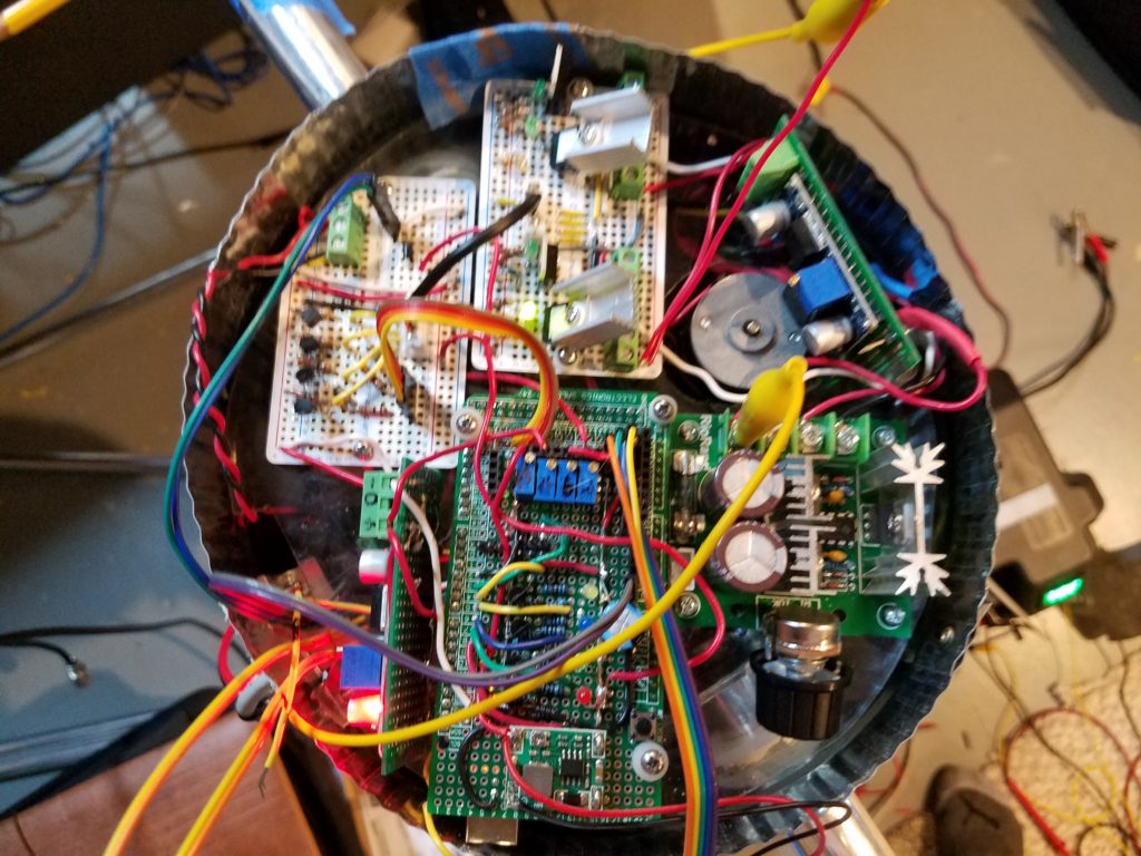
Note: Using 2N3904 NPN’s as a simple switches inverts the signal. HIGH on Base, is now LOW output on Collector. We then get enough drive to control the larger current circuit with the FET1 & FET2. Little confusing, but you get used to it. I use (4) 30amp FET switches. At max I’m switching <2 amps, so heat sinks are really not necessary, but usually a good idea. Below is the control board.
At 12 O’clock is the logic driver board. The (4) 2N3904’s, receive HIGH & LOW from the Mega 2560 and control the power circuitry at 6 O’clock. The 2 FET’s with heat sinks will be on most of the time for system power and camera circuits. To keep them happy, I put on some small heat sinks.
In a nutshell, the EOT switches keep the system from rotating out of control for some odd reason. It took a few clock cycles of my thinkolator, but the results are a success.
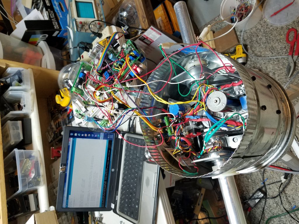
Checking out the new power controller module.
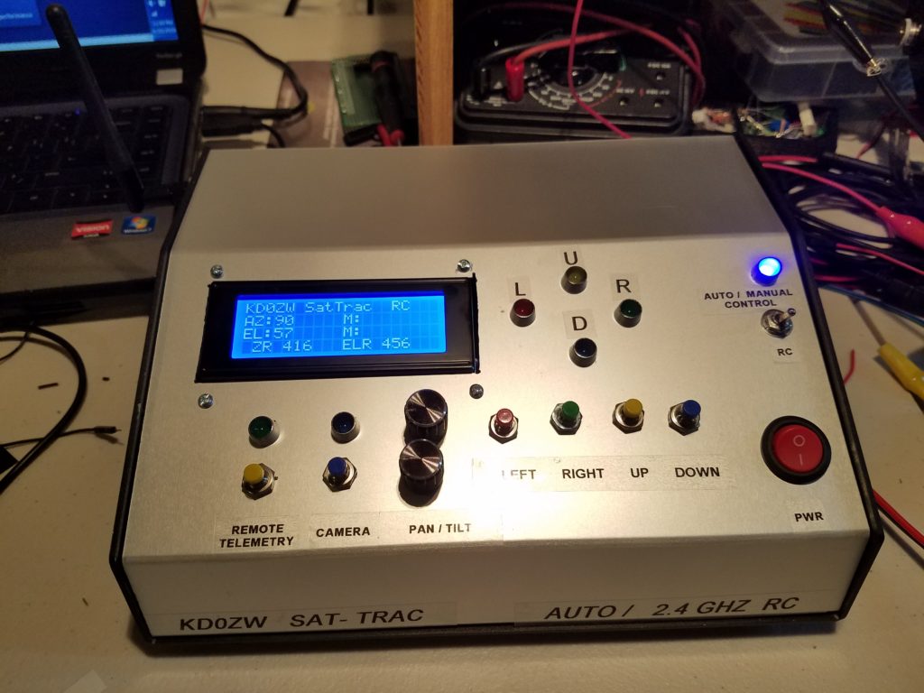
Wow, that really improved the efficiency. Below is Sat Trac base controller. The computer system will run SatPC32 GS232 commands.
More to come: Stay tuned…
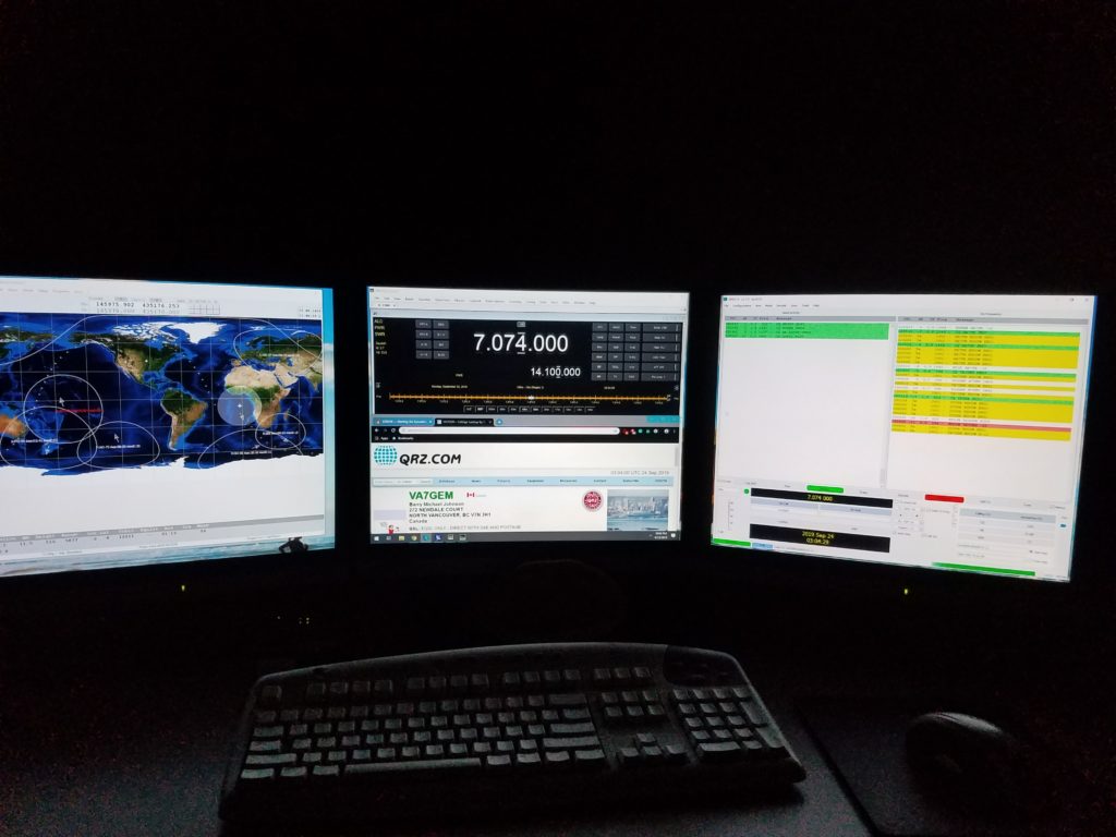
Custom water cooled 8-core AMD8350 4.3ghz base system. Running Ham Radio Deluxe, Sat32PC, and WSJT 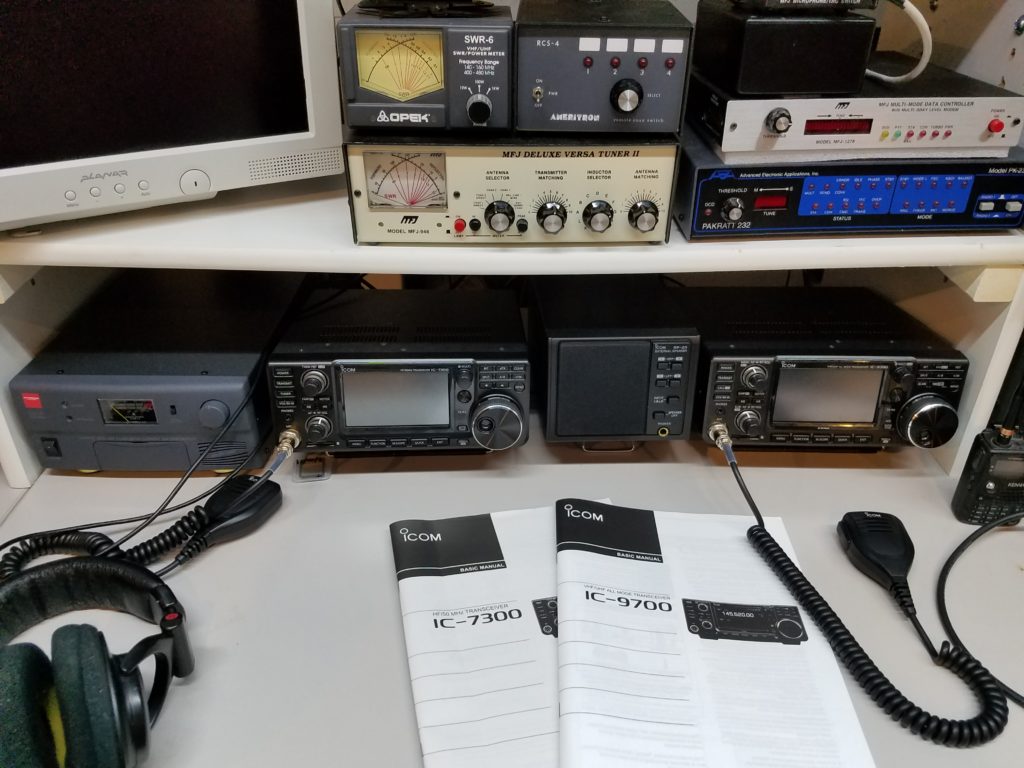
Interface to the computer is an IC-7300 & IC-9700 KD0ZW SAT TRAC Direct connect or 2.4ghz RC connect using GS232 commands. 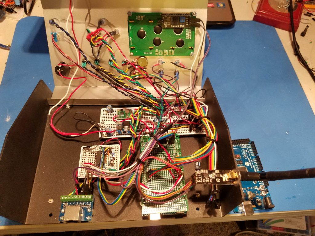
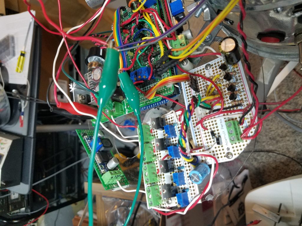
Flip the lid into the SAT-TRAC. Runs with Mega 2560, debounced switches and linked to the remote by 8 element cable or 2.4Ghz. 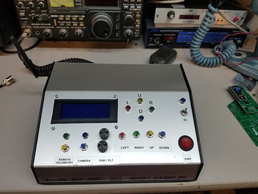
New computer control/2.4 Ghz RF controlled AZEL KD0ZW Sat Trac
More to come soon as I button it up and deploy it to the deck… Stay tuned.