SAT-TRAC – Part 4 Controlling the hardware
Part 4: Controlling the Hardware
Okay, we got the base rotating, and elevator elevating. Now what? Well, we need to interpret the rotary motion and convert it to degrees. Basically, millivolts to degrees. This calls for a single board controller (SBC). What about a single-board computer like a Raspberry Pi(Rpi)? Well, our criteria are directing us to be energy efficient. Rpi has a lot of power. However, interpreting analog sensors would require additional signal processing to work properly. And, it pulls more power. The Arduino is efficient, easy to interface, and supported with many common peripherals like LCD’s, servos, RF transceivers, etc. Also, it can be easily breadboarded, programmed and it’s inexpensive. So, I decided to use the Arduino Nano for the base controller and another one for the remote SAT-TRAC to handle system health monitoring, and send and receive data at 2.4Ghz.
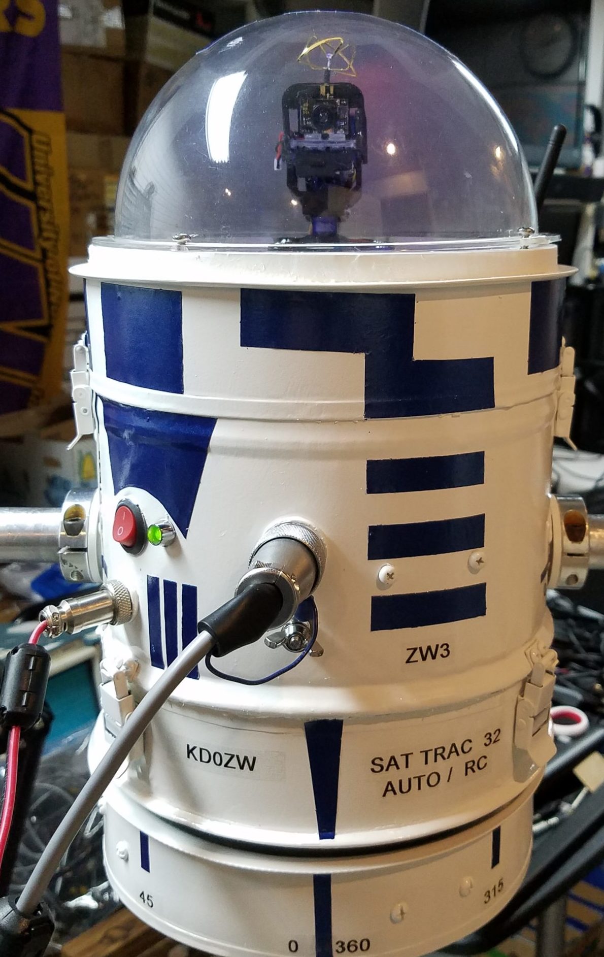
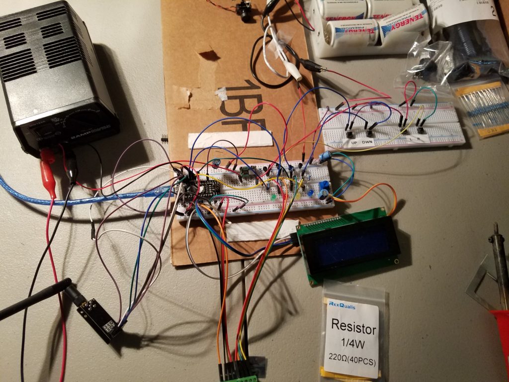
First, I created a base unit like this:
The manual switches worked nicely to control the AZ and EL. The unit jumped when I sent it to the maximum speed in either direction. Too responsive and jarring to the unit. Gadzooks, a speed controller is necessary. Heading out to amazon, I found a sweet FET DC controller at a reasonable price and wired it in. Now we have silky smooth directivity. Totally adjustable. Now, can I use the laptop to control it? This could be a make or break situation. I went to the web in search of direction. I stumbled upon Tom Doyle’s (W9KE) site SimpleSat Rotor controller at tomdoyle.org. He was using Yaesu -232 commands (a standard) and the Arduino Mega to control the Yaesu controller and ultimately control the AZEL unit outside. Well, I wasn’t using the GS5500 control unit but I was planning on using the SATPC32 program. Tom being the great Ham that he is, provided Arduino coding to handle the interface from the laptop to the Arduino. I have jumped a big hurdle. I extracted the Arduino interface code and began to write code to display the position is degrees, and moves directed by the SATPC32 program. Everything worked surprisingly well, however, scaling the precision pots to give accurate position over 3 turns of the pot or about 1.75V would require a steady DC reference voltage. So to make it as accurate as possible, I decided to use a separate mini power supply with 1000uf caps to ensure a low ripple from the 5V DC source. The A/D ports could then give a reasonable number between 0-1023. Raw values are also sent to the LCD screen so you can get an idea of what the pots sending and the computer is seeing.
Starting on this journey on Jan 15, 2019, and working on this project when I felt up to it, it was time to try the interface to the laptop and the remote SAT-TRAC. It’s April and it’s been a battle. With the boom connected and 2 lightweight Diamond antennas mounted. I’m using a Diamond 5 element 2mtr beam (9.0dBi) and a Diamond 10 element 70cm beam(13dBi). Both aprox. 1.4 lbs and perfect for the SAT-TRAC. Clearing space in the rec-room, the commands from the laptop started to show on the LCD screen and it positioned it self +/- 1 to 3 degrees. The amp meter showed 150ma draw at 12v and 100ma on standby. Very reasonable in my opinion. Success with manual and computer control! And it was smooth, very smooth…. Did I make that? Most of the design criteria met, it’s time to add the RC & telemetry capabilities.