On the Bench — Work in Process
As Amateur Radio enthusiasts, we always have a project in mind or in progress… Well mine, the SAT-Trac featuring the droid ‘ZW3’ has been an ongoing project for me. It is extremely rewarding to get the project completed, and it meets your expectations! Sometimes we miss the mark, but we keep after it until we reach our objective.
In Jan 2019, I started off on an adventure to build a computer-controlled satellite tracking mechanism pushing way outside of my comfort zone. With a couple of steps forward and a couple of steps back, the KD0ZW SAT-Trac system was born and deployed on 10/6/2020. Here is ZW3 as a baby. RC controlled from 100ft away, or directly connected, ZW3 boldly went where I’ve never gone before… space the ultimate frontier, this is the story of ZW3.
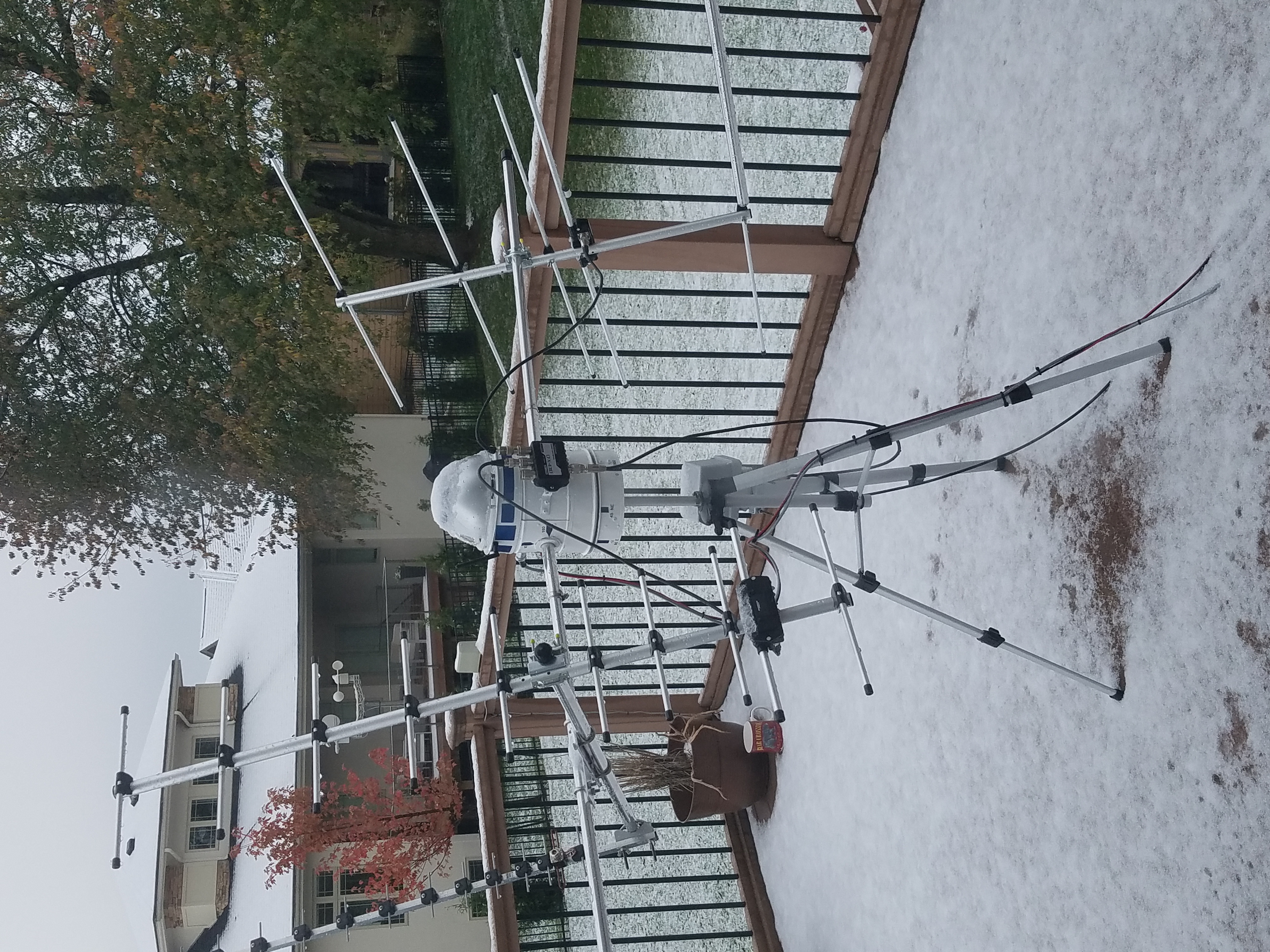
Wow, instantly fellow hams referred to me as that guy with an R2D2 Sat Tracker… Okay, it’s ZW3, a long-lost relative twice removed…
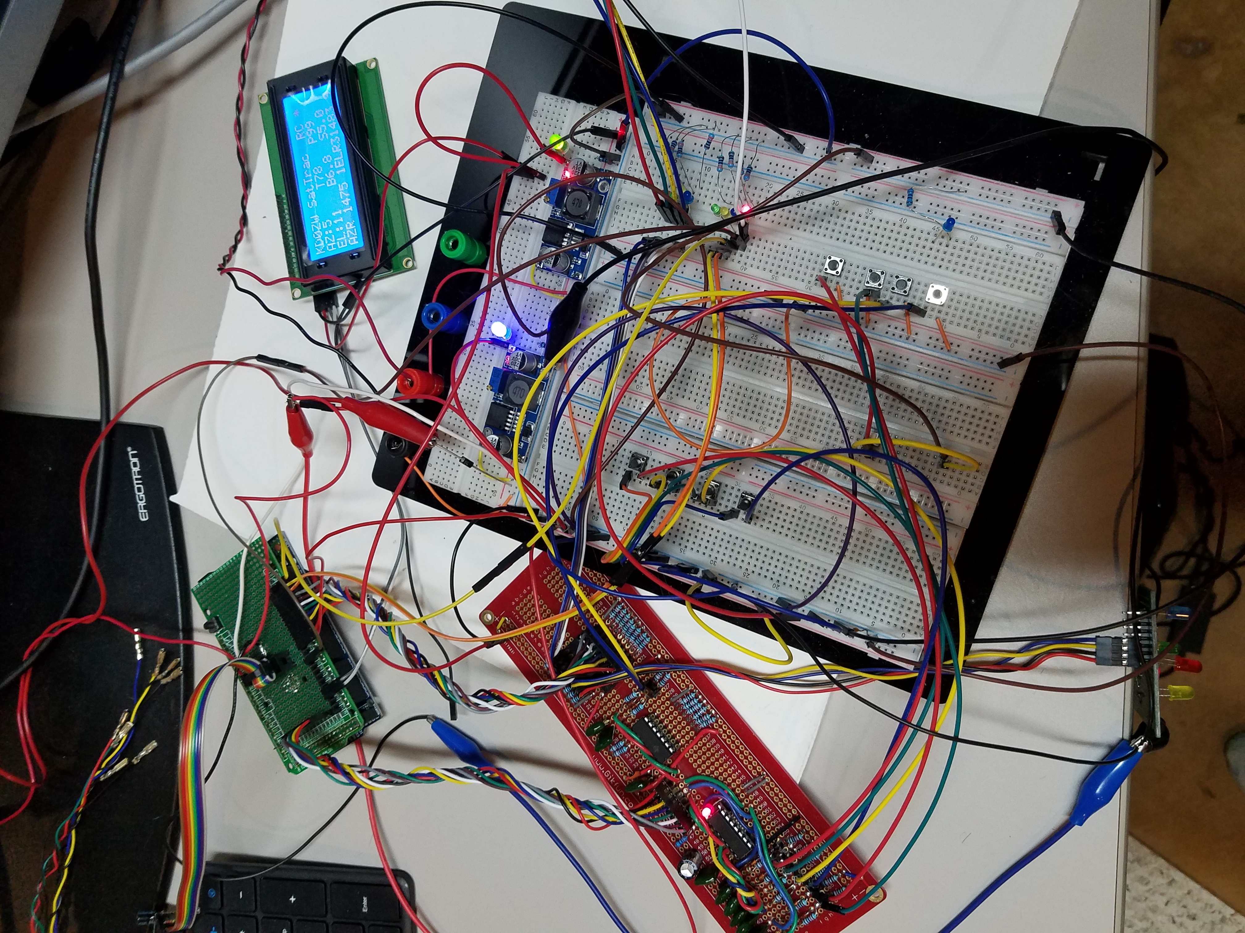
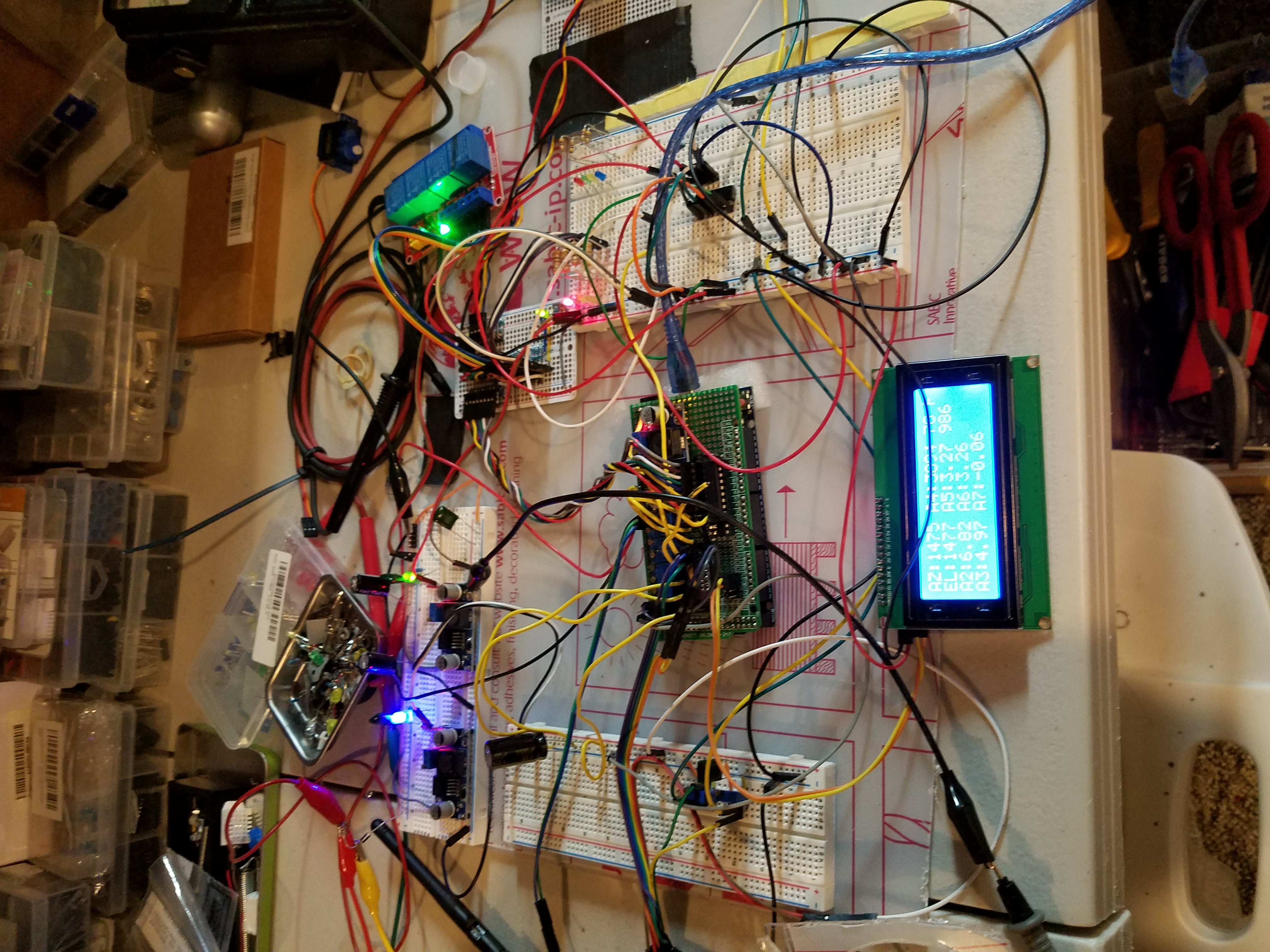
Where am I going with this? Bigger, Better & Faster of course. ZW3 & host controller, are getting an upgrade to the Arduino Due 32-bit single-board computer (SBC). Going from a 5v system to a 3.3v presents a lot of challenges. After the bus-mastering, debouncing, power supply tweaking, C++ programming, and of course testing, we are almost there. Why is this taking so long? Well doing something like this gets your mind turning. If it could do this or that building on previous experiences. Well, the KD0ZW SAT-Trac 32 system is attempting to address some items that have been not up to snuff. For Example:
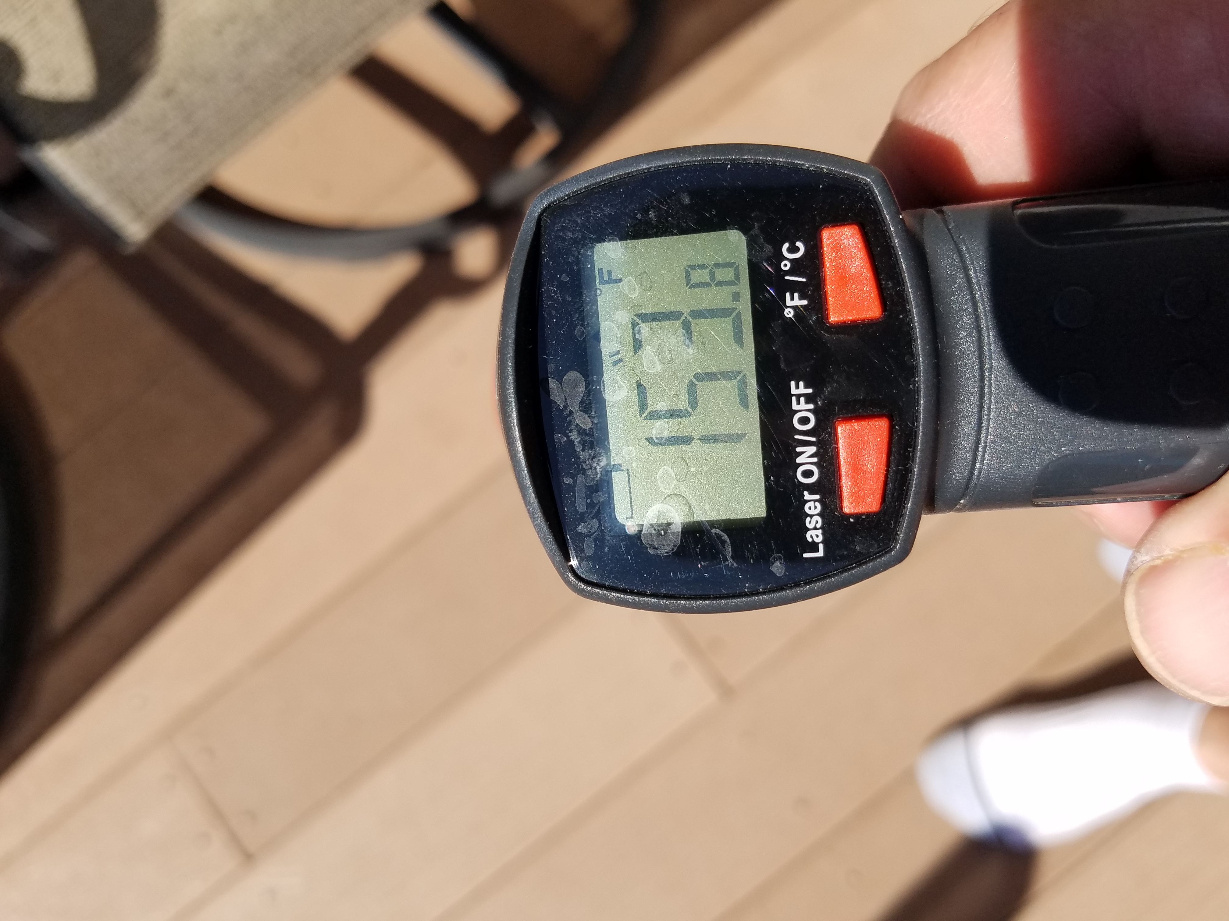
1). Precision pots don’t like 150F to -20F temp swings and tend to be non-linear causing 30-40 degree offset errors when sampling 100ft away! — Solution: Implement (2) AS5600 no-touch magnet pots for AZ & EL! No effect from extreme temps, and physical wear! Very accurate too! However, it requires an i2C bus multiplexer due to the fact they have the same bus addresses. Not a show stopper… just something else
2). The 8-bit version uses inverse logic on all control lines to ZW3 and is 5V. So to move the tracker, for example, an AZ line is taken to zero volts when moving CW or CCW. In a perfect world, not a big deal. But if something shakes loose or the elements short a control line, ZW3 could spin until it breaks. End of Travel (EOT) precautions have been implemented months ago… A Better solution? Yep, Positive logic. All control lines are at 0V until they are pulled up to 3.3V by the controller. At 100ft how can we possibly control ZW3 with 3.3V?… just something else. ZW3 and the controller are using 4 bus mastering chips to coordinate the commands from the controller directly and from the RC transceiver. It protects the Arduino Due from higher voltages as well as is capable of driving a logic-level FET.
3). ZW3 has a 5.8ghz camera… However, it would be nice to see an echo of the commands in real time just so I can feel it is under control. Indicator lights are added under the bubble so I can see them on camera…just something else!
4). Taking the jitter out of the analog lines… After trading emails with Chris, VA3ECO, I got some guidance on how to keep the analog lines from bouncing 5-10 degrees. I added a small value resistor inline and added a 10uf cap. That calmed things down to 3-5 degree swings. This worked, but the cap slowed the change value a little bit. Going to work on the programming side, I did some high-speed sampling of the analog lines at the controller by using an ADC>DMA access algorithm and retrieved 20-30 samples very quickly. Averaging them, I’m seeing the jitter about completely eliminated. This worked well even though the tracker was running at about 1 rpm. The extra horsepower for the Due really helps. A concern but now a non-issue! Just something else!
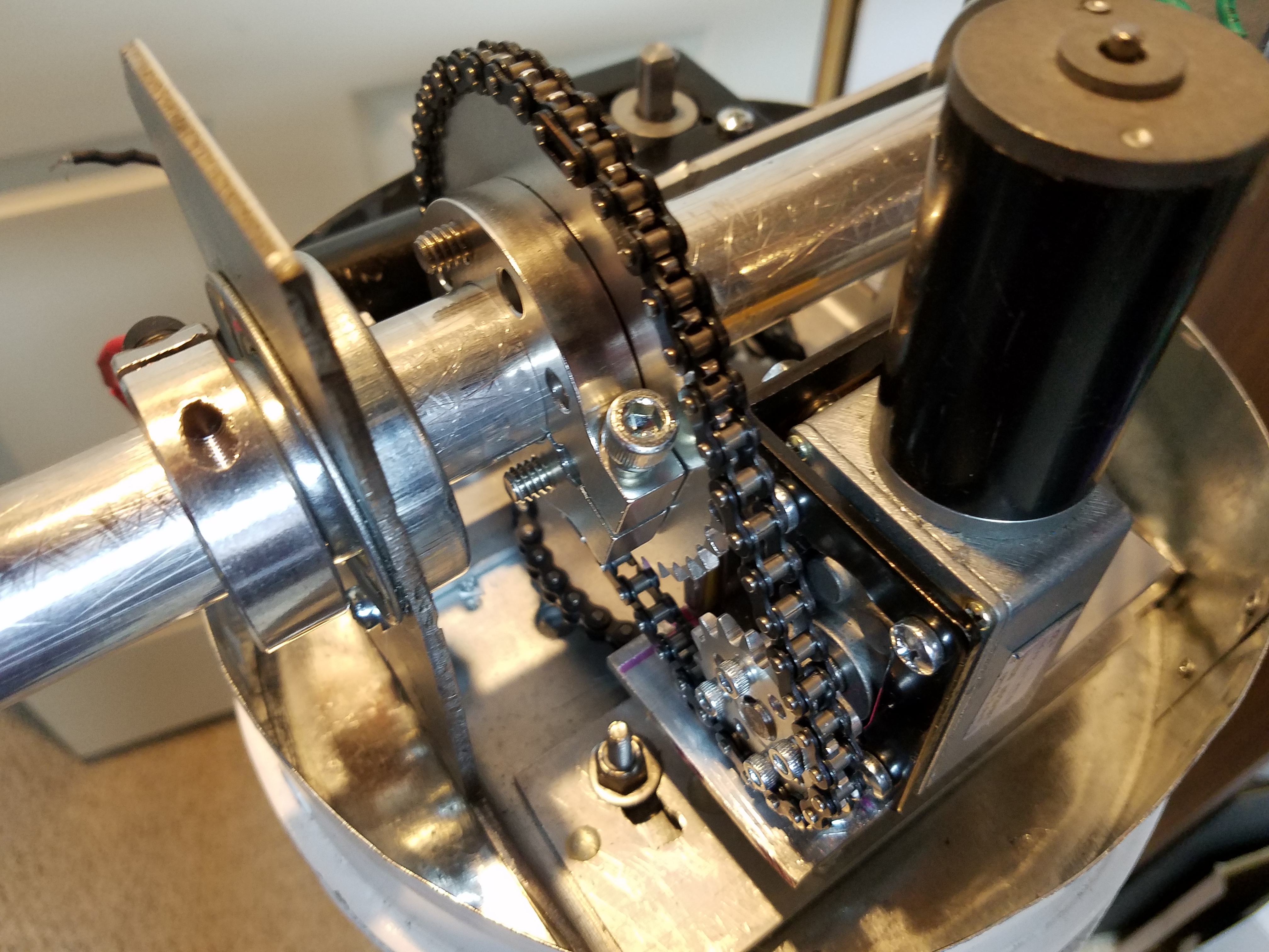
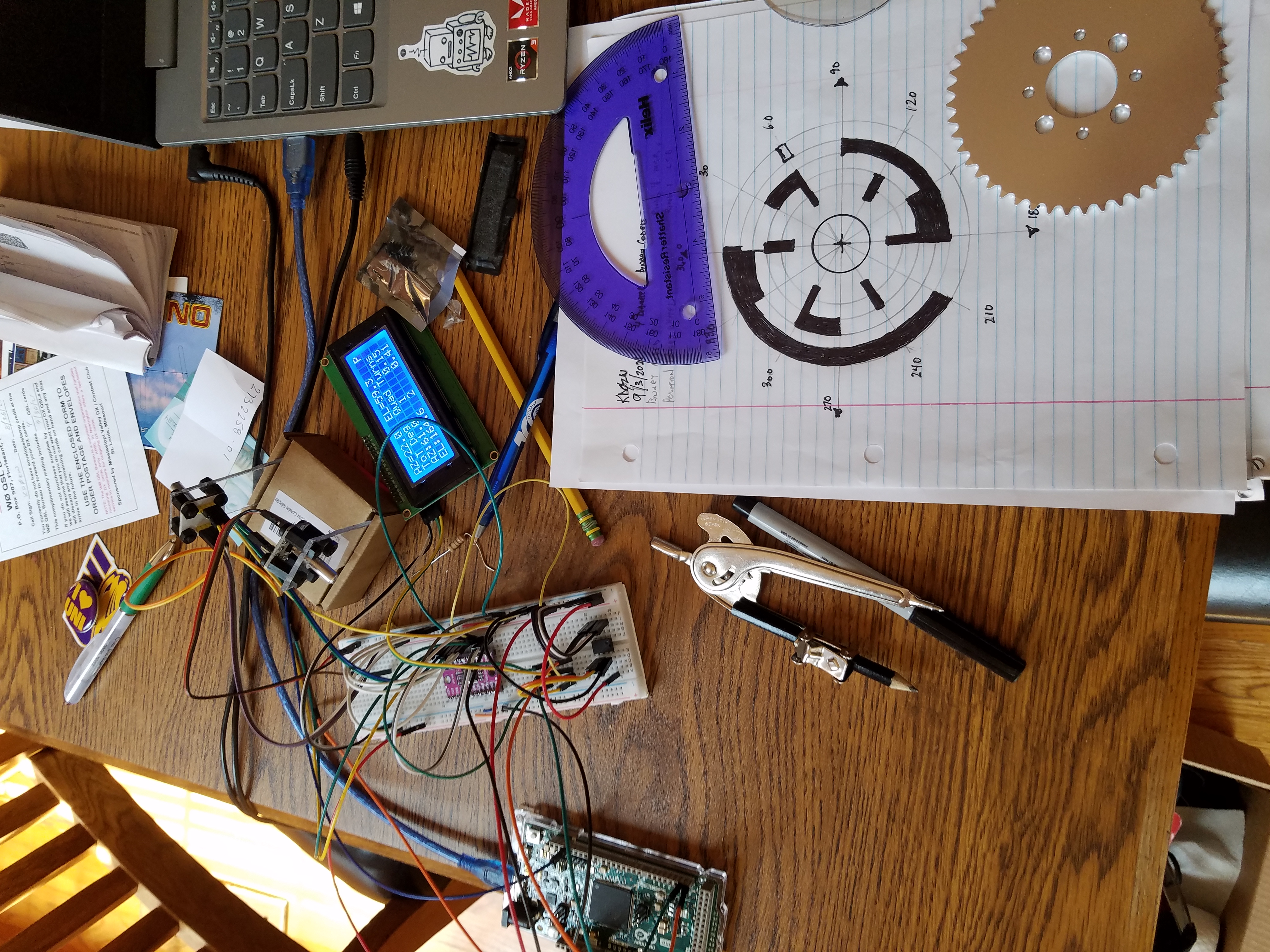
5). New pots will not feel the environmental extremes. However, due to torque requirements, a 2.5:1 gearing was engineered to work with a 10rpm worm drive motor and speed controller to get silky smooth transitions with AZ & EL. What it means is the motor has to turn 2.5 rotations for a 360-degree AZ and 1.25 rotations for the EL! Okay, not an issue for pots that can handle 10 turns, but what about an AS5600? Well, after one rotation it starts all over again. Well, the Curious Scientist on youtube has this perplexing issue with his stepper motor attachment. So, he writes software to tare off the position where it is left off and starts at 0. So, I park at 180,90 and shut off the system. When I start it up, 180,90 becomes 0,0. You guessed it, just something else!

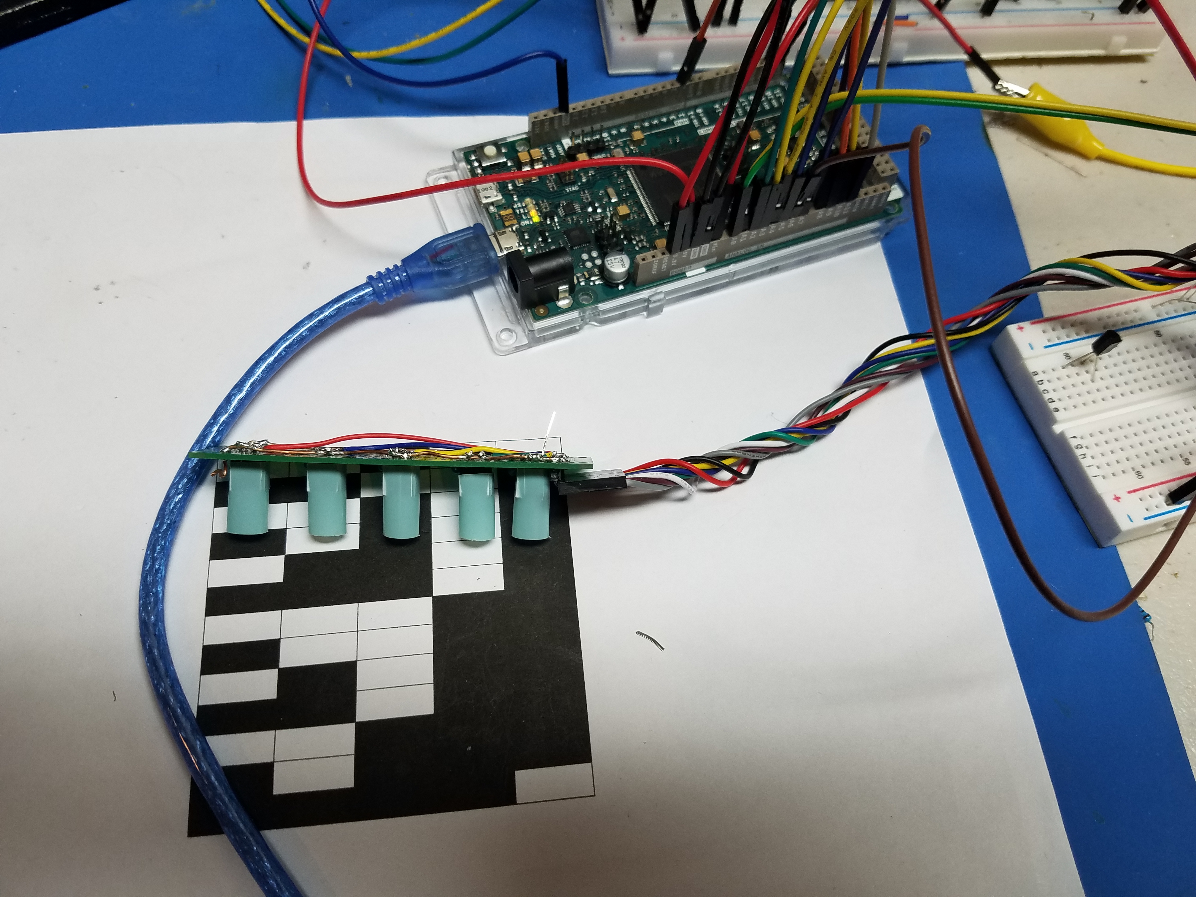
Okay, here is something interesting. Using (4) ITR20001/T mini IR sensors, I have constructed a cylindrical 4-sensor binary (black & white) background from a spreadsheet and will mount the sensors to their appropriate area at a distance of ~3-5mmm. When we start up the system, I access an EEPROM chip added to the system to see where it was parked. Then through programming, I read multiple samples of the cylinder binary representation and translate it to a decimal number and the associated degree position. From its last know park position, a watchdog timer is calculated for the move. The system automatically reads the cylinder moving to 0,0, and then zero’s the controller’s read values to 0,0. We are automatically calibrated. Should it overshoot for some odd reason, the watchdog would shut off the move to where it should be! Going from dark to light changes the 0-4095 expected values by ~800-1000. The software will help determine the HIGH (1) or LOW (0) situation.
6). In the past, I experienced a buck converter 3A power supply getting wonky. So, defective voltage regulation could cause voltages to creep up over 5V or in this new case 3.3V. SBCs don’t like higher voltages than they are specified at. And, I don’t like to replace SBC at $40 a wack. So, just something else. All control lines have 3.3V Zenors to protect the unseen voltage monster. Also, bus master chips are 5v tolerant…so we have extra protection.
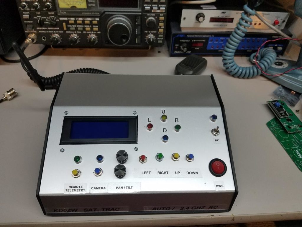
Okay, that’s enough for now… here is the controller in the final stages of completion:
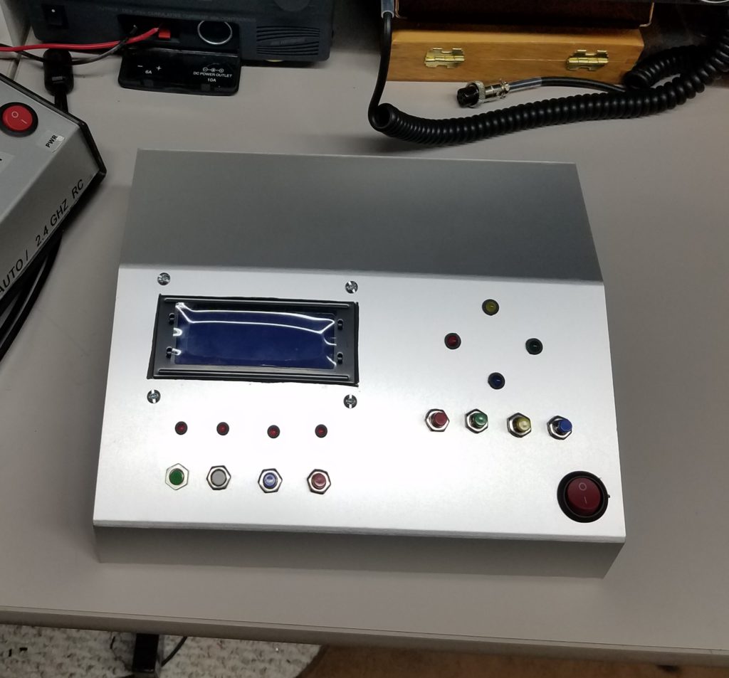
The new outer shell of the KD0ZW Sat-Trac 32 controller.
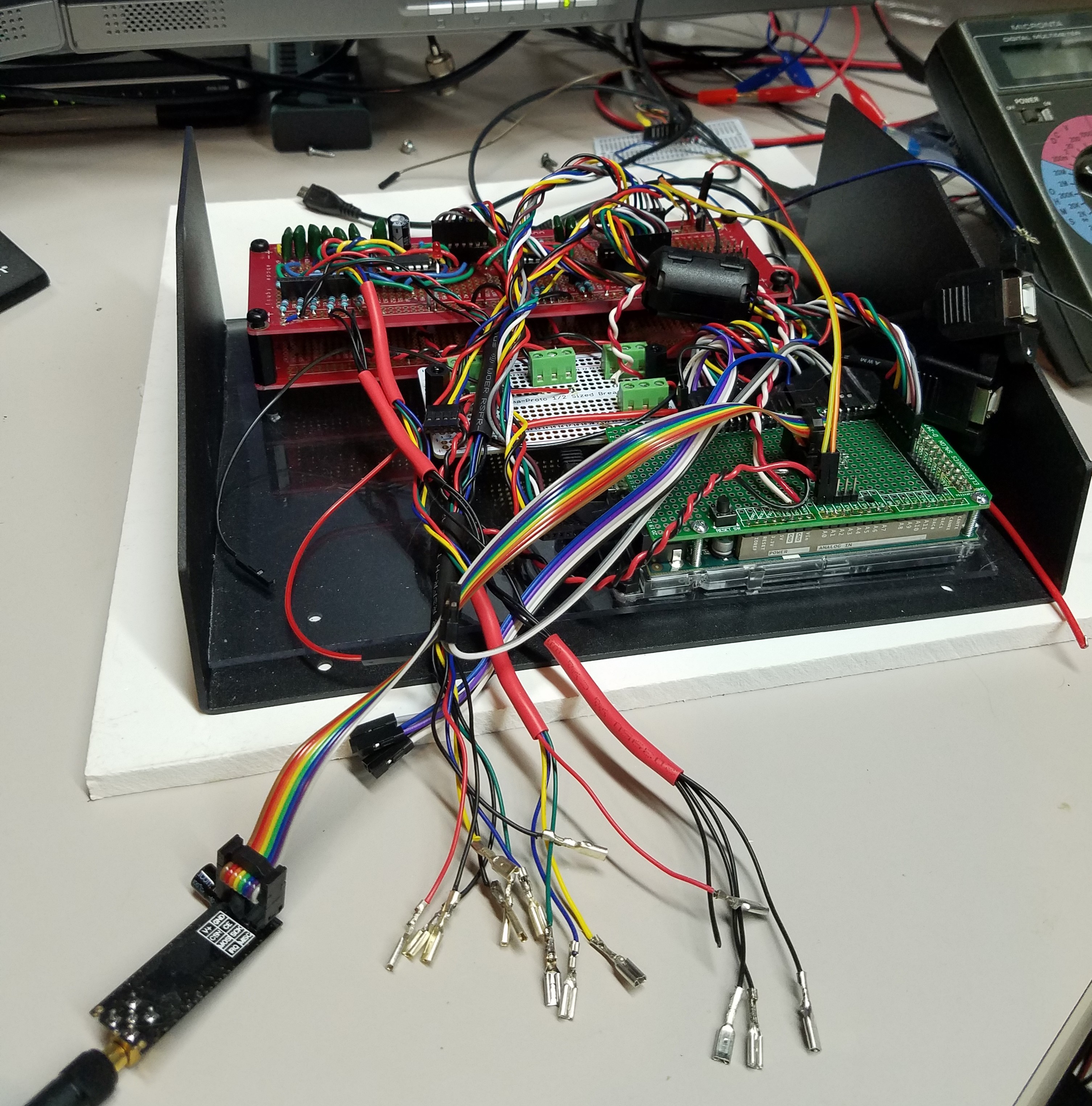
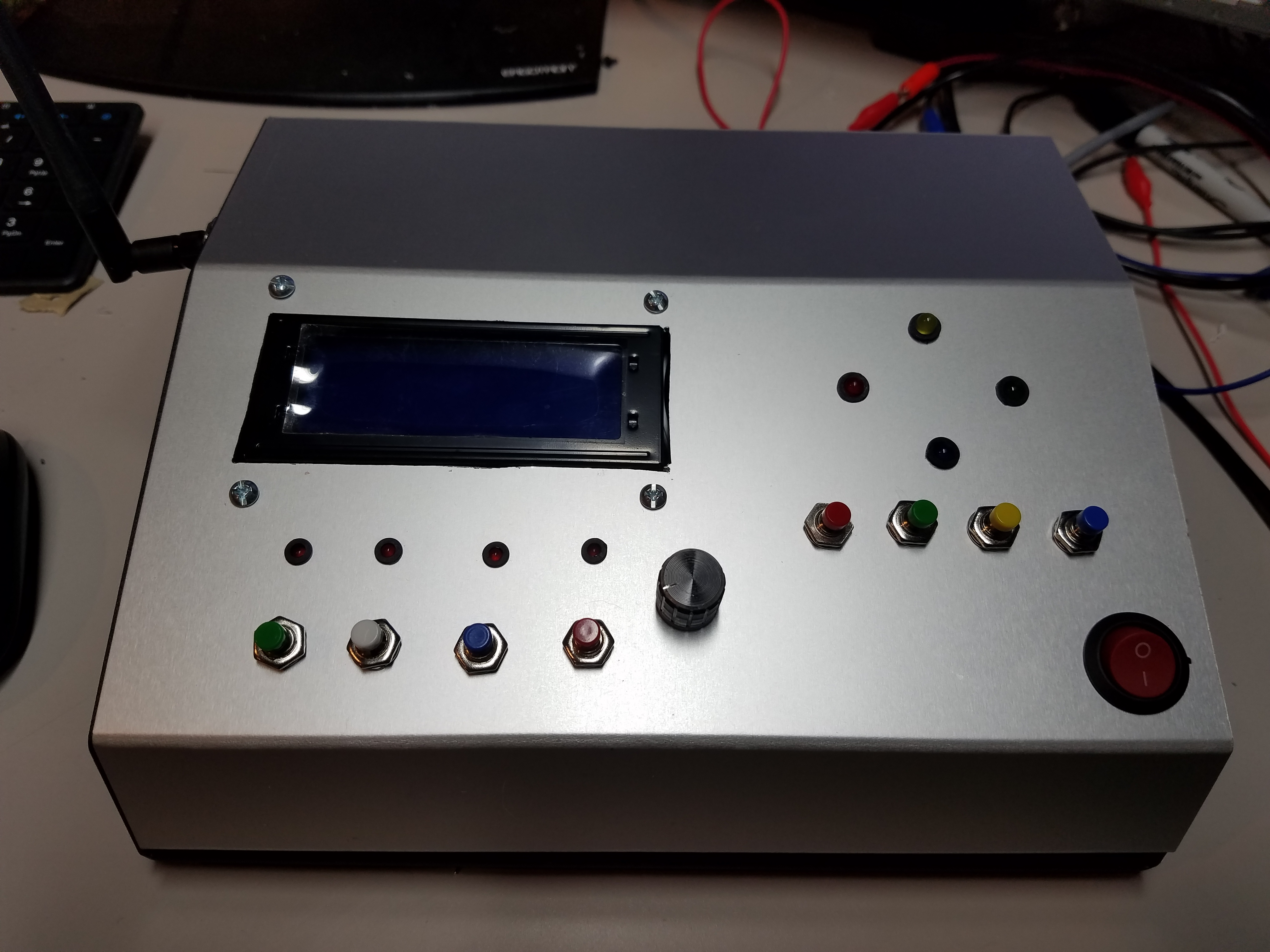
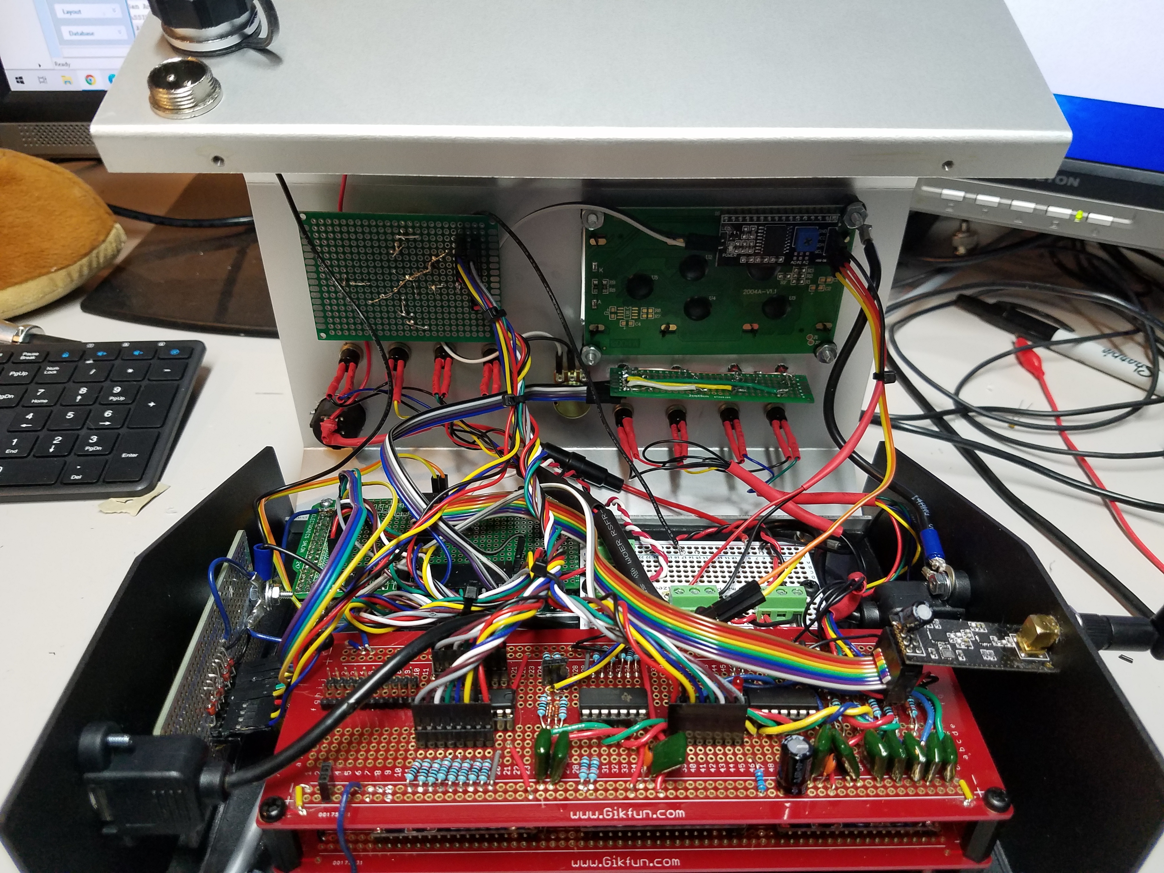
I’m getting close to putting the lid on the controller. New features on this 32-bit controller!
- Directly connect with 9 elements shielded control line or 2.4ghz RC 1000m range.
- 3 separate filtered power supplies for 3.3, 5, & 8 volts — add’l filtering and protection circuits.
- Polarity switching of the antenna from the controller. CP or (Vert. or Horz.).
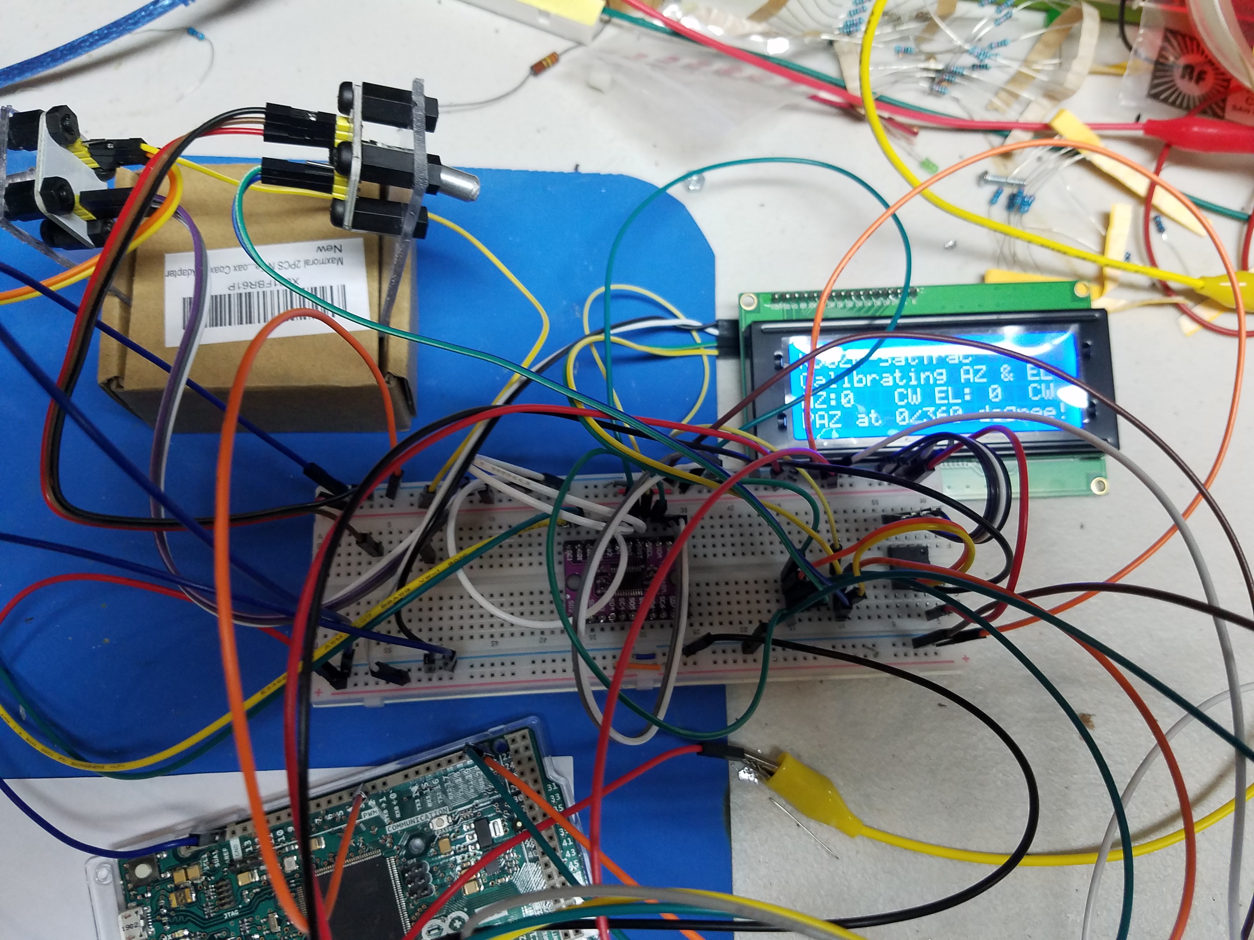
- Auto calibration on startup. Using ITR200001/T to zero AZ & EL.
- MCU is an original Arduino Due 32bit — Both programming and controlling USB ports on the controller.
- 20×4 dimmable LCD display.
- DAC outputs to, or RC, to the controller from the remotes, AS5600 sensors.
- Fast ADC/DMA analog sampling for better 12-bit accuracy of AZ & EL when directly connected.
- Temp & Altitude info as well as digital information from remote BMP280 & (2) AS5600 sensors.
- Uses generic GS232 commands from SAT32PC software.
- 6x performance increase over 8-bit Arduino Mega 2560.
- uses the existing 9-element control line.
- Auto temp controlled cooling & heating.
- Camera control — 5.8ghz FPV 200mw camera
Okay… if you are ready… I know I’m ready after about 4 months of programming fabricating, painting, detailing, and testing… Here we go… Click Here for the New KD0ZW SAT TRAC 32…