Upgrading the Coax for Satellite operations
Previously sharing my experience as a noob on satellites, I mentioned adding ‘L’ band or 23cm capabilities since the IC-9700 has a port and puts out 10 watts at 1296mhz. So, you put out 10 watts to 92ft of LMR 240uf and what arrives at the antenna? Not much… Here is an interesting analysis of what poor VHF & UHF coax performance will do to your output:
Below is my current arrangement from the transmitter to the antenna: Note: connectors are N type for all connectors and triplexers have insertion losses for each band.
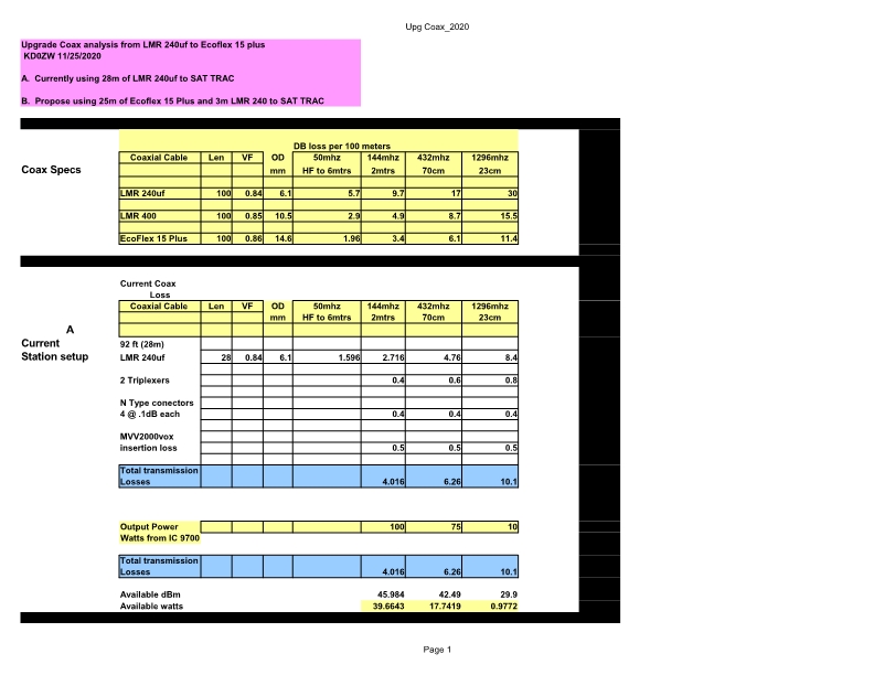
Wow, 100watts at 2m from the transceiver delivers about 40 watts to the antenna? And, 75watts at 70cm dwindles to 17.74 watts to the antenna. And wait for it, 10 watts at 23cm ends up at .977 watts at the antenna… I’m thinking there is room for improvement! Looks like most of the wattage is getting attenuated in the coax and the connectors! What can we do?
1). We can upgrade to LMR400 or compatible and cut the losses in half.
2). We can upgrade to an LMR600 or compatible like Ecoflex 15 plus and cut the losses to a third!
3). Or, Just deal with it and know it’s very lossy.
I don’t think ignoring the current performance of LMR 240uf is the best solution… For HF it’s fine… For VHF & UHF it’s not good for long runs. Basically, we’re going to throw money at it. LMR600 requires LMR approved connectors and special tools. Or maybe Ecoflex +15 could work and be outfitted with beefy N-type connectors that anybody can put together. I like Ecoflex 15 plus. It’s the answer. Can I get it in the states? Noooo. So I can buy it from the mfg SSB Electronics GmbH. YES! So, I bought 25m of it and had it shipped in. Note: The shipping cost is almost as much as the coax. With 2 beefy N-type connectors and 25m of coax shipped it amounted to about 3.90/ft USD. Below is a picture comparison of Ecoflex 15 plus to LMR240 Ultra Flex.
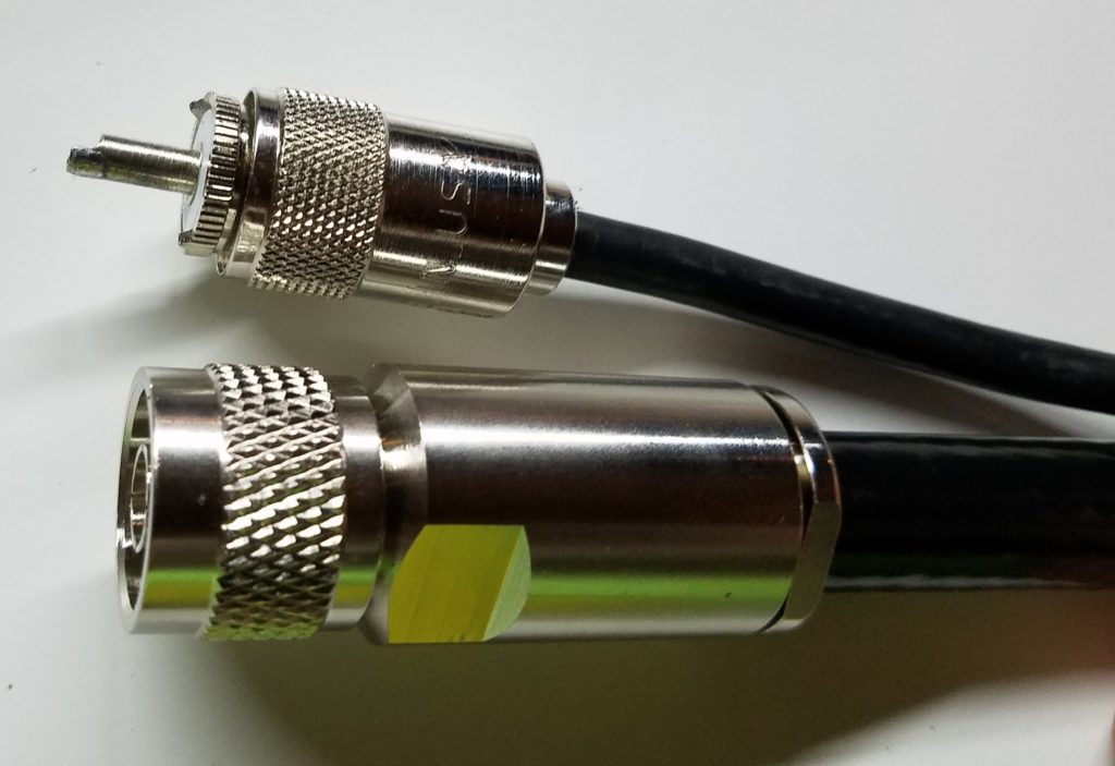
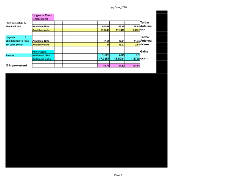
The last line of the above table showed the “available watts” to the antenna. So, 40% of the 100-watt output at 2m was reaching the antenna. It gets worse as the frequency goes up. At 70cm, 23.6% of the 75 watts reach the antenna, and at 23cm, less than 10% get to the antenna. PL259’s are a no-go also. They are leaky and sometimes referred to as speed bumps to RF at these frequencies. Out they go and N-types on everything. N-type will limit your losses. Serious Satellite & Earth Moon Earth (EME) operators put their preamps and power amps at the antenna to avoid the losses from long coaxial runs and use sequencers to shut off the preamps while transmitting. Well, that complicates the whole portable idea. Or does it? Well, I still enjoy the shack/cave environment. So let’s run the numbers of 25m of Ecoflex 15+ and 3 m of 240uf to the SAT Trac droid on the deck. Here’s how that shakes out:
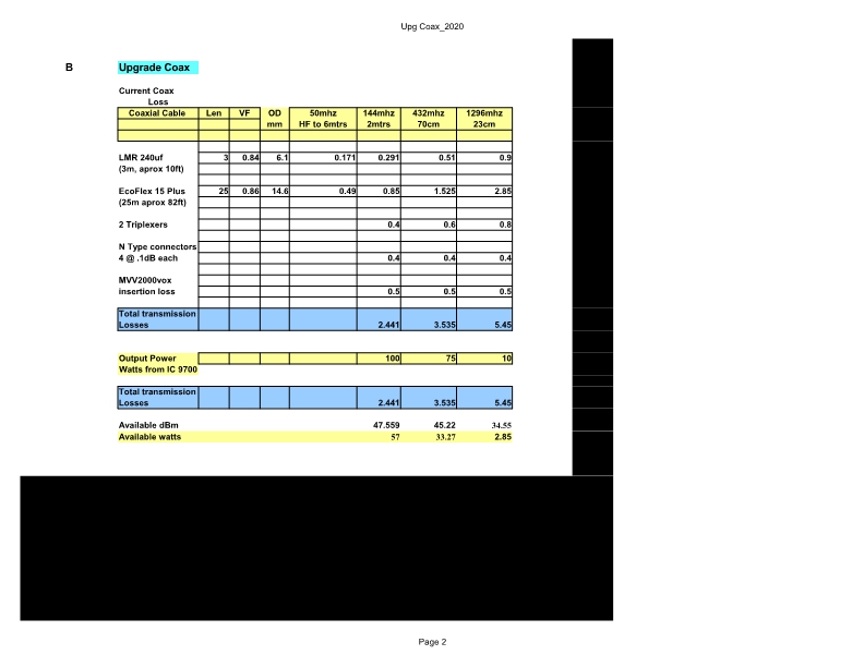
What an improvement. We have gained 43.7% more watts available to the antenna on 2m, 87% more power on 70cm, and 191% gain on 23cm available watts. Looks like it was the right move! Let’s next look at the EIRP results:
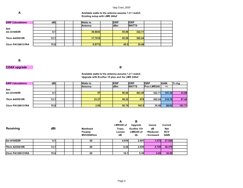
The change has been worth the effort. EIRP has increased dramatically with the high dbi yagi and the lower losses in the coax. So, what have I noticed with the lower transmission losses and increased EIRP? Well, a couple of things were pretty evident. Signal to noise was apparent. I was hearing satellites at 12 to 15 degrees elevation. Now I hear them at 8 to 10 degrees elevation when I really don’t have a clear line of sight until approx. 20 degrees. Secondly, I like to work the higher altitude birds. The height gives me more talk time and if the elevation is 0 to 90 degrees a clear uplink can be established and 8 to 10 stations can be worked. Increased EIRP is evident. Last week on a Sunday night I caught RS-44 at 130 azimuths, and 23 degrees elevation. The satellite was about 200 miles east of Florida and 1500km or 1000 miles up. I was seeing a 2 to 3 S unit downlink….. wow! At my location, the signal had to go through lots of trees and atmosphere to get to the bird. And of course, obstacles on the downlink are helped with a 20db masthead preamp and a 10db preamp on the transceiver. No shortage of amplification on the receive. Anyway, a back of napkin trig calculation was made and my 2 m signal traveled 1700 miles to reach the bird, and the 5-watt transmitter on RS-44 was arriving back at S 2-3. I believe the higher quality coax made a big difference both on the uplink and downlink. Here is how the change stacked up on the downlink side of the equation:
There it is. A 1.575 to 4.65 dB change in signal strength on the downlink. However, I’m still not completely happy with 23cm. 3 watts out and a 5.45 dB transmission loss may not do it. Maybe a small amp on the droid could multiply the 3 watts up to the bird. What’s next? Well, a couple of things. I’m exploring adding another 2m and 70cm yagi on the beam and configuring it for RHCP. Plans are being made and parts being ordered for a more robust Azimuth and Elevation system. ZW3 can handle winds up to 35 mph. Gust up to 50 have given it a challenge. My goal will be to make it as resilient as possible and keeping it in the 8″ diameter container. That’s it for this adventure…
73,
Mike
KD0ZW

